
Instructions

60
1
2
3 4
5
6
7
4
2.1
EN
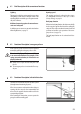
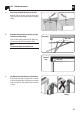
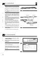
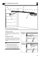
10.9 (A) Installation of the header bracket (1)
NOTE!
The header bracket (1) must be aligned with the mid-
point of the door.
Legend
1 = Lintel bracket
2 = Bolt (6 x 80 mm) with hexagon nut
2.1 = Protective sleeve
3 = Hexagon screw (8 x 60 mm)
4 = Rail
1. Mark out the position of the header bracket (1)
and drill the mounting holes (e. g. with a 10 mm
masonry drill bit).
2. Screw the header bracket (1) tight with the en-
closed hexagon screws (3) [8 x 60 mm].
3. Subsequently guide the rail (4) and protective
sleeve (2.1) between the ends of the lintel
bracket (1) and push the screw (2) [6 x 80 mm]
through from the outside.
4. Finally secure the rail (4) by tightening the
hexagon nut.
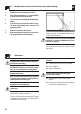
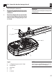
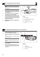
10.10 (B) Installation of the fixing bracket (5) at the drive head (7)
1. Push the fixing bracket (5) onto the rail (4), as
close to the drive head (7) as possible.
2. Mark the mounting holes for the fixing bracket
(5).
In order to do so, lift the entire construction and push
it against the ceiling.
NOTE!
Ensure that the rail (4) is aligned with the centre of
the door.
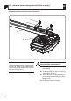
3. Drill the mounting holes (e. g. with a 10 mm
masonry drill bit).
4. Finally screw the fixing bracket (5) to the ga-
rage ceiling with the enclosed hexagon screws
(8 x 60 mm).
Legend
4 = Rail
5 = Fixing brackets
6 = Hexagon screw (8 x 60 mm)
7 = Drive head