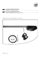
DE Garagentorantrieb RolloPort SX5 DuoFern Original Betriebs- und Montageanleitung......................................................................................................1 EN Garage door drives RolloPort SX5 DuoFern Translation of the Original Operating and Assembly Manual........................................................................41 Artikel-Nr. / Item no: 4505 90 61 (dreiteilige Schiene / three-section rail) VBD 607-1-1 (10.
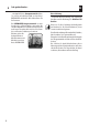
i Sehr geehrte Kunden... ...mit dem Kauf dieses Garagentorantriebs haben Sie sich für ein Qualitätsprodukt aus dem Hause RADEMACHER entschieden. Wir danken Ihnen für Ihr Vertrauen. Der RADEMACHER Garagentorantrieb ist unter Aspekten des größten Komforts entstanden. Mit einem kompromisslosen Qualitätsanspruch und nach langen Versuchsreihen sind wir stolz, Ihnen dieses innovative Produkt zu präsentieren. Dahinter stehen alle hochqualifizierten Mitarbeiterinnen und Mitarbeiter aus dem Hause RADEMACHER.
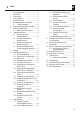
i Inhalt i 1. 2. 3. 4. 5. Sehr geehrte Kunden... ..................................2 Lieferumfang ..................................4 Gesamtansicht ..................................5 Zeichenerklärung ..................................6 Sicherheitshinweise ..................................6 Bestimmungsgemäße Verwendung..................7 5.1 Einsatzbedingungen..............................8 6. Nicht bestimmungsgemäße Verwendung.........8 7. Zulässige Garagentotypen.................................
i 1. Lieferumfang DE Garage door drives RolloPort SX5 DuoFern Translation of the Original Operating and Assembly Manual .......................................................................41 VBD 607-1-1 (10.17) Garagentorantrieb RolloPort SX5 DuoFern Original Betriebs- und Montageanleitung .....................................................................................................1 12. EN 2. DE 11. Artikel-Nr. / Item no: 4505 90 61 (dreiteilige Schiene / three-section rail) 1. 3.
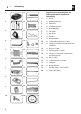
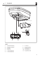
i 2. Gesamtansicht DE 1 2 4 5 7 8 9 3 6 11 10 Legende 1 2 3 4 5 6 = = = = = = Antrieb, inkl. Beleuchtung Schutzhaube (abnehmbar) Handsender Kontroll-LED 1. Taste des Handsenders 2.
i STOP 3. Zeichenerklärung DE Lebensgefahr durch Stromschlag. Wichtige Sicherheitshinweise, deren Nichtbeachtung kann zu Sachschäden führen. Dieses Zeichen weist Sie auf Gefahren bei Arbeiten an elektrischen Anschlüssen, Bauteilen etc. hin. Es fordert Sicherheitsmaßnahmen zum Schutz von Gesundheit und Leben der betroffenen Person. Beachten und befolgen Sie bitte alle so gekennzeichneten Hinweise.
i 4. Sicherheitshinweise Durch unsachgemäßen Gebrauch besteht erhöhte Verletzungsgefahr. ◆◆ Greifen Sie nie in das fahrende Tor oder in bewegte Teile. ◆◆ Das Tor darf ohne zusätzliche Sicherheitseinrichtungen (z. B. Lichtschranke) niemals außerhalb der Sichtweite bewegt werden, s. Seite 33. ◆◆ Unterweisen Sie alle Personen, die das Garagentor bedienen, im sicheren Gebrauch des Garagentorantriebs.
i 5. Bestimmungsgemäße Verwendung Eine mangelhafte Wartung kann zur Gefährdung von Personen durch Beschädigung Ihres Garagentorantriebs, der zugehörigen Sicherheitseinrichtungen und der Garagentoranlage führen. ◆◆ Halten Sie alle Wartungshinintervalle ein, s Seite 12. ◆◆ Führen Sie eine regelmäßige Prüfung der Sicherheitseinrichtungen durch, s. Seite 12. i 5.1 8 6. Die Nichtbeachtung aller Angaben in dieser Anleitung kann zu schweren Verletzungen von Personen führen, z.B.
i 6. Nicht bestimmungsgemäße Verwendung Der RolloPort SX5 DuoFern darf nicht ohne zusätzliche Lichtschranke verwendet werden, s. Seite 33. Durch unsachgemäße bauliche Veränderungen besteht Verletzungsgefahr. Nehmen Sie keine baulichen Veränderungen am Antrieb, dem Garagentor oder eventuell vorhandenen Sicherheitseinrichtungen vor, die von den in dieser Anleitung beschriebenen Maßnahmen abweichen. Solche Veränderungen gefährden die Betriebssicherheit. i 7.
i 8. Funktionsbeschreibung Der RolloPort SX5 DuoFern ist ein elektronischer Garagentorantrieb und für alle gängigen Schwing- und Sektionaltore (s. Seite 9) einsetzbar. Flexible Montagemöglichkeiten Die um 90° drehbare Antriebseinheit bietet flexible Montagemöglichkeiten. Ein leiser Zahnriemenantrieb sorgt für sichere Kraftübertragung. Umfangreiche Komfortfunktionen Der RolloPort SX5 DuoFern bietet umfangreiche Komfortfunktionen (s. Kap. 8.1) zur individuellen Einstellung vor Ort.
i 8.1 Kurzbeschreibung der Komfortfunktionen Beleuchtung Der Garagentorantrieb verfügt über eine interne energiesparende LED-Beleuchtung, die nach jedem Schaltimpuls eingeschaltet wird und automatisch nach 3 Minuten wieder ausgeht. Zusätzliche Anschlussmöglichkeiten für externes Zubehör und Sicherheitseinheit Zusätzlich können Sie einen externen Schalter, sowie eine Infrarot-Lichtschranke anschließen, s. Seite 33.
8.4 1. 2. 3. 4. 5. 6. Monatliche Prüfung der Hinderniserkennung (Kraftbegrenzung) Fahren Sie das Tor in die Endstellung auf. Legen Sie einen 50 mm hohen Gegenstand, z. B. einen Holzklotz, in die Laufrichtung des Tores. Schließen Sie das Tor durch Betätigen des Handsenders. Stößt das Tor beim Schließen gegen ein Hindernis, stoppt der Antrieb automatisch und öffnet das Garagentor vollständig. Entfernen Sie anschließend das Hindernis.
10. Wichtige Montagehinweise Wichtige Anweisungen für eine sichere Montage. Alle Montageanweisungen befolgen. Eine falsche Montage kann zu ernsthaften Verletzungen führen. Prüfen Sie vor der Montage ... ◆◆ ..., ob Ihr Antrieb für den Garagentortyp und die Garagentorhöhe geeignet ist. ◆◆ ...das Tor auf seinen einwandfreien mechanischen Zustand. Das Tor muss leichtgängig sein und sich im Gleichgewicht befinden. Überprüfen Sie, ob es sich ordnungsgemäß öffnet und schließt. ◆◆ Öffnen Sie das Tor ca.
10.1 Notwendige Werkzeuge Sie benötigen folgende Werkzeuge: 10.2 Entfernen der Torverriegelungen 1. Demontieren Sie alle senkrechten und waagerechten Torverriegelungen. HINWEIS! Heben Sie die „alten“ Torverriegelungen gut auf. Falls Sie den Garagentorantrieb einmal demontieren, müssen Sie diese wieder montieren, um den Originalzustand des Tores wieder herzustellen.
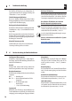
10.3 Maß nehmen 1. Tormitte ausmessen und markieren Markieren Sie die Tormitte wie gezeigt an der Toroberkante, am Torsturz und an der Garagendecke. 2. Abstand zwischen Toroberkante und Decke ermitteln Schließen Sie das Tor langsam und messen Sie den Abstand zwischen Toroberkante und Decke. DE Schwingtor min. 4 cm HINWEIS! Der Mindestabstand sollte 4 cm betragen. Sektionaltor min. 4 cm 3.
10.4 Zusammenbau der Schienen DE HINWEIS! Der RolloPort SX5 DuoFern wird mit drei Schienen geliefert: ◆◆ zwei Endstücke, inkl. vormontiertem Zahnriemen ◆◆ ein Mittelteil (ohne Zahnriemen) mit zwei Verbindern. 1. 2. 3. 4. 5. 1 2 3 Legen Sie die beiden Endstücke mit dem vormontierten Zahnriemen so auf den Boden, dass der Zahnriemen möglichst gerade zwischen ihnen verläuft.
10.6 Verbindung des Antriebsgehäuses mit der Schiene 1. 2. 3. Setzen Sie zuerst den Vielzahnverbinder (5) ein. Setzen Sie die Schiene (4) mit dem innenliegenden Ritzel (ab Werk in der Schiene vormontiert) über den Verbinder (5). Stecken Sie zwei Haltewinkel (2) auf die Schiene (4) und schrauben Sie diese mit den beiliegenden Sechskant-Blechschrauben (6 x 15 mm) am Antriebsgehäuse fest. DE WICHTIG! Achten Sie darauf, dass der Mikroschalter (3) bei der Montage der Schiene nicht beschädigt wird.
10.7 Verbindung des Antriebsgehäuses mit der Schiene (90° Montage) DE Alternative Montage des Antriebs quer zur Schiene. 1 2 4 5 3 HINWEIS! Der Mikroschalter (3) muss immer am Ende der Schiene positioniert sein. Daher muss der Mikroschalter (3) bei der Quermontage des Antriebs entsprechend umgesetzt werden, s. Abbildung oben. 18 Beim allen Arbeiten am Mikroschalter (3) besteht Lebensgefahr durch Stromschlag. ◆◆ Lassen Sie den Mikroschalter (3) nur durch eine zugelassene Elektrofachkraft umsetzen.
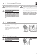
10.8 Befestigung des Antriebs und der Schiene DE (D) (A) (B) (C) A / B / C / D, siehe folgende Seiten Sturzmontage Die Montage sollte vorzugsweise am Sturz erfolgen, da so die auftretenden Kräfte optimal aufgenommen werden können. Sturzmontage min. 1,5 cm Deckenmontage Für die Deckenmontage sollten Sie den Sturzwinkel um 90 Grad drehen und weiter innen an der Garagendecke befestigen. Dadurch kann der gesamte Schienenweg genutzt werden.
10.9 (A) Montage des Sturzwinkels (1) DE HINWEIS! Der Sturzwinkel (1) muss mittig zum Tor montiert werden. 1. 2. 3. 4. Zeichnen Sie die Position des Sturzwinkels (1) an und bohren Sie die Montagelöcher (z.B. mit einem 10 mm Steinbohrer). Schrauben Sie den Sturzwinkel (1) mit den beiliegenden Sechskantschrauben (3) [8 x 60 mm] fest. Führen Sie anschließend die Schiene (4) und die Schutzhülse (2.1) zwischen die Enden des Sturzwinkels (1) und schieben Sie die Schraube (2) [6 x 80 mm] von außen hindurch.
10.11 (C) Montage des Torwinkels (8) HINWEIS! ◆◆ Wir empfehlen Ihnen den Torwinkel (8) vorzugsweise am Torrahmen zu befestigen. ◆◆ Für Kunststoff- oder dünnwandige Holztore sind zusätzliche Verstrebungen nötig, um eine Beschädigung des Tores zu vermeiden. Sprechen Sie in diesem Fall mit Ihrem Torlieferanten. ◆◆ Verwenden Sie zur Montage des Torwinkels (8) schon vorhandene Bohrlöcher, falls möglich.
10.11 (C) Montage des Torwinkels (8) 3. 4. DE Schrauben Sie den Torwinkel (8) mit den beiliegenden Sechskant-Blechschrauben (8 x 15 mm) am Rahmen fest. Befestigen Sie zum Schluss den Toranbinder (12) mit dem beiliegenden Bolzen (9) am Torwinkel (8). 12 HINWEIS! ◆◆ Ab Werk ist schon ein gerader Toranbinder vormontiert, dieser ist fest mit der Schiene verbunden.
10.13 Wichtige Hinweise nach der Montage DE ◆◆ Stellen Sie sicher, dass die Anlage nach der Montage ordnungsgemäß eingestellt ist und dass der Antrieb reversiert (zurückfährt), falls das Tor einen 50 mm hohen auf dem Boden befindlichen Gegenstand berührt (für Antriebe, die über ein Einklemmschutzsystem verfügen, das bei Kontakt mit der Torunterkante anspricht), s. Seite 12.
11.1 Endpunkte einstellen / Oberen Endpunkt einstellen Die falsche Reihenfolge bei der Einstellung der Endpunkte führt zu Fehlfunktionen. Halten Sie unbedingt die vorgegebene Einstellreihenfolge ein. DE Korrekte Einstellreihenfolge: 1. oberen Endpunkt einstellen 2. unteren Endpunkt einstellen 1. Drücken Sie „P“ für ca. 5 Sekunden. 2. Der Antrieb erzeugt einen Signalton und zeigt „1“. 3. Drücken Sie „P“, „1“ blinkt. 4. Drücken Sie „+“ oder drücken Sie „–“. 5. Das Tor fährt auf oder zu. 6.
11.3 Referenzfahrt zur Kraftmessung durchführen DE Während der Referenzfahrt besteht Verletzungsgefahr, da der Antrieb sehr große Kräfte entwickelt. 1. Drücken Sie „+“, in der Anzeige erscheint „3“. 2. Drücken Sie „P“, „3“ blinkt. 3. Das Tor hebt sich automatisch. 4. Drücken Sie nach dem Stopp 2 x auf „P“. 5. Das Tor senkt sich. 6. Drücken Sie nach dem Stopp „P“ um die Information zu speichern. Im Anschluss wird die „0“ zyklisch angezeigt und der Antrieb in den Ruhezustand versetzt. 7.
11.4 Kraftbegrenzung bei Bedarf anpassen HINWEIS! Der Antrieb ist ab Werk auf Stufe 3 eingestellt. Bei Bedarf (z.B. bei zu niedrigem Kraftniveau) können Sie die Kraftbegrenzung nachträglich anpassen. 1. Drücken Sie „P“ für ca. 5 Sekunden. DE Ein zu niedriges Kraftniveau beeinträchtigt die Torbewegung. Besonders wenn die mechanische Struktur des Tores nicht gut ausbalanciert ist. 2. Drücken Sie auf „+“ (evtl. mehrfach drücken) bis die „4“ angezeigt wird. 3.
11.5 Alarmeinstellung DE (auch via HomePilot® einstellbar) Wenn der Alarm eingeschaltet ist, erzeugt der Antrieb einen Signalton, wenn das Tor länger als 10 Minuten geöffnet ist. Der Signalton ertönt alle 10 Minuten für 30 Sekunden. Beenden des Alarmtons: Drücken Sie die Torsteuerungstaste, um das Tor vollständig zu schließen. 1. Drücken Sie „P“ für ca. 5 Sekunden. 2. Drücken Sie auf „+“. (evtl. mehrfach drücken) bis die „5“ angezeigt wird. 3. Drücken Sie „P“, die Anzeige ist „0“.
11.6 Automatische Schließzeiteinstellung DE (auch via HomePilot® einstellbar) 5. Drücken Sie „+“ und wählen Sie die gewünschte Schließzeit: 1 = 30 s 5 = 150 s 2 = 60 s 6 = 180 s 3 = 90 s 7 = 210 s 4 = 120 s 8 = 240 s (Maximum) 6. Drücken Sie „P“, um die Einstellung zu speichern. 7. Programmierung abschließen, (s. Seite 31 / Methode 2) oder weiter mit nächster Einstellung 11.
11.8 Einstellen der Auffahrgeschwindigkeit DE (auch via HomePilot® einstellbar) Mit Hilfe dieser Funktion können Sie die Geschwindigkeit der Aufbewegung je nach individuellem Bedarf einstellen. Die Einstellung der Auffahrgeschwindigkeit erfolgt in cm/s (Zentimetern pro Sekunde). 1. Drücken Sie „P“ für ca. 5 Sekunden. 2. Drücken Sie auf „+“ (evtl. mehrfach drücken) bis die „8“ angezeigt wird. 3. Drücken Sie „P“, die Anzeige ist „1“.
11.9 Einschalten der Back-Jump Funktion DE (auch via HomePilot® einstellbar) Funktion Nach dem Schließen entlastet die Back-Jump Funktion den Antriebsstrang durch ein kurzes (10 mm) Fahren in Gegenrichtung. 30 1. Drücken Sie „P“ für ca. 5 Sekunden. 2. Drücken Sie auf „+“ (evtl. mehrfach drücken) bis „9“ angezeigt wird. 3. Drücken Sie „P“, die Anzeige ist „0“. (0 = Aus = Werkseinstellung) 4. Drücken Sie „+“, die Anzeige ist „1“. (1 = Ein = Die BackJump Funktion ist eingeschaltet.) 5.
11.10 Programmierung abschließen HINWEIS! Bitte beachten: Dieser abschließende Schritt muss ausgeführt werden, da die gespeicherten Informationen sonst verloren gehen. DE Für den RolloPort SX5 DuoFern gilt: Die Programmierung muss abgeschlossen sein, damit Sie Einstellungen im DuoFern Netzwerk bzw. im HomePilot® vornehmen können. Sie können die Programmierung wie folgt auf zwei Arten abschließen: Methode 1: Diese Methode unbedingt nach der Referenzfahrt durchführen 1.
12. Handsender und /oder DuoFern HomePilot® an- und abmelden DE Handsender oder DuoFern Sender anmelden: Werksseitig sind beide Handsender bereits am Garagentorantrieb auf der großen Taste angemeldet. Wenn Sie einen weiteren Handsender anmelden möchten oder einen bereits im Lieferumfang enthaltenen Handsender abgemeldet haben und wieder anmelden möchten, gehen Sie wie folgt vor. 1. Drücken Sie „S“ für ca. 2 Sekunden und lassen Sie dann los. 4. Einen DuoFern Sender oder einen HomePilot® anmelden.
13. Verwendung und Montage einer Lichtschranke Als zusätzliche Sicherheitseinrichtung können Sie an den RolloPort SX5 DuoFern Garagentorantrieb eine Lichtschranke anschließen (Art.-Nr. 8000 00 51). Zusätzlich gilt für den RolloPort SX5 DuoFern ◆◆ Garagentorantriebe mit automatischem Zulauf (z.B. RolloPort SX5 DuoFern) müssen neben einer serienmäßig vorhandenen Kraftbegrenzung, über eine zusätzlich angeschlossene Sicherheitseinrichtung (z. B. Lichtschranke) verfügen.
14.
15. Manueller Betrieb des Tores DE Im Falle eines Stromausfalls: 1. Wollen Sie das Tor bei Stromausfall manuell bedienen, müssen Sie am Seil der Notentriegelung ziehen, damit diese das Tor vom Antrieb entriegelt. Danach können Sie das Tor frei bewegen. Es besteht Verletzungsgefahr. Das Tor kann beim Entriegeln unkontrolliert herunterfallen (z.B. wenn das Tor sich nicht im Gleichgewicht befindet). ◆◆ Schließen oder öffnen Sie nach jeder Entriegelung das Tor immer vollständig.
16. Anleitung für den Anwender Hinweise für den Einsatz ◆◆ Überprüfen Sie das Antriebssystem, um festzustellen, ob es sich beim ersten Einsatz des Garagentorantriebs leicht bewegt. ◆◆ Überprüfen Sie nach einiger Zeit im Gebrauch regelmäßig, ob das Tor beim Öffnen/Schließen horizontal bleibt und ob die Feder genügend Kraft hat, um das Tor zu heben. Fügen Sie zu allen beweglichen Teilen regelmäßig eine geeignete Menge Schmiermittel hinzu.
TD 17.
i 38 18. Fehlerbehebung DE Fehler Ursachen Lösung Der Antrieb funktioniert nicht. 1. Der Stecker ist nicht sicher eingesteckt. 2. Die Sicherung hat ausgelöst. 1. Netzstecker in Steckdose stecken. 2. Ursache von einem Techniker prüfen lassen, danach die Sicherung wieder einschalten. Der Handsender kann den Antrieb nicht bedienen. 1. Der Handsender wurde eventuell falsch oder gar nicht angemeldet. 2. Die Batterie ist leer. 1. Melden Sie den Handsender neu an, siehe Seite 32. 2.
i 19. Vereinfachte EU-Konformitätserklärung Hiermit erklärt die RADEMACHER Geräte-Elektronik GmbH, dass der RolloPort SX5 DuoFern den Richtlinien 2006/42/EG (Maschinenrichtlinie) und 2014/53/ EU (Funkanlagenrichtlinie) entspricht. i 20. DE Der vollständige Text der EU-Konformitätserklärung liegt dem Produkt bei und ist beim Hersteller hinterlegt.
21. Garantiebedingungen RADEMACHER Geräte-Elektronik GmbH gibt eine 36monatige Garantie für Neugeräte, die entsprechend der Einbauanleitung montiert wurden. Von der Garantie abgedeckt sind alle Konstruktionsfehler, Materialfehler und Fabrikationsfehler. Ihre gesetzlichen Gewährleistungsansprüche bleiben von dieser Garantie unberührt.
DE Garagentorantrieb RolloPort SX5 DuoFern Original Betriebs- und Montageanleitung......................................................................................................... 1 EN Garage door drives RolloPort SX5 DuoFern Translation of the Original Operating and Assembly Manual........................................................................... 41 Item No.: 4505 90 61 (three-section rail) VBD 607-1-1 (10.
i 42 Dear Customer, EN with your purchase of this garage door drive, you have decided in favour of a quality product manufactured by RADEMACHER. Thank you for the trust you have placed in us. These instructions... The RADEMACHER garage door drive has been designed in an effort to achieve the greatest possible ease of operation. Having applied uncompromising quality standards and thorough testing, we are proud to be able to present this innovative product to you.
i Contents i 1. 2. 3. 4. 5. Dear Customer, ................................42 Scope of delivery ................................44 General view ................................45 Key to symbols ................................46 Safety information ................................46 Proper use ................................47 5.1 Operating conditions...........................48 6. Improper use ................................48 7. Approved garage door types...........................49 7.
i 1. Scope of delivery Garage door drives RolloPort SX5 DuoFern Translation of the Original Operating and Assembly Manual .......................................................................41 VBD 607-1-1 (10.17) Garagentorantrieb RolloPort SX5 DuoFern Original Betriebs- und Montageanleitung .....................................................................................................1 EN 12. Artikel-Nr. / Item no: 4505 90 61 (dreiteilige Schiene / three-section rail) 2. 11. DE 1. 3.
i 2.
i 3. Key to symbols EN Risk of fatal electric shock. Important safety information which can lead to property damage if not observed. This sign warns of danger when working on electrical connections, components, etc. It requires that safety precautions be taken to protect the life and health of the person concerned. STOP Please pay particular attention and carefully follow all instructions marked with this symbol.
i 4. Safety information Incorrect use leads to an increased risk of injury. ◆◆ Never reach into the moving door or into moving parts. ◆◆ The door should never be operated out of sight without additional safety equipment (e.g. light barrier), see page 73. ◆◆ Instruct all persons who operate the garage door in the safe use of the garage door drive.
i 5. Proper use A lack of maintenance can lead to personal injury through damage to your garage door drive, the associated safety devices and the garage door system. ◆◆ Observe all maintenance intervals, see page 52. ◆◆ Test the safety equipment regularly, see page 52. i 5.1 6. Pay attention to all of the information.
i 6. Improper use The RolloPort SX5 DuoFern may not be used without additional light barriers, see page 73. Incorrectly performed structural alterations result in the risk of injury. Do not carry out any structural alterations to the drive, the garage door or any existing safety equipment which deviate from the measures described in this manual. Such alterations endanger the operating safety. i 7. EN If a wicket door is installed, the door position must be monitored.
i 8. Functional description The RolloPort SX5 DuoFern is a electronic garage door driver suitable for use with all standard up-and-over and sectional doors (see page 49). Flexible installation options The 90° rotatable drive unit offers flexible installation options. The quiet-operation belt drive provides secure power transmission. Extensive convenience functions The RolloPort SX5 DuoFern offer extensive convenience functions (see chap. 8.1) for individual customisation on-site.
i 8.1 Brief description of the convenience functions Lighting The garage door drive has an integrated energy-saving LED lighting system which is switched on after each switching impulse and which goes off again automatically after 3 minutes. Additional connecting options for external accessories and safety unit In addition you can connect an external switch and an infrared light barrier, see page 73. EN Opening speed: The opening speed can be adjusted in three stages.
8.4 1. 2. 3. 4. 5. 6. Monthly checks on the obstacle detection system (power limiting) Run the door into the fully open position. Place a 50 mm high object, e. g. a wooden block, in the direction of travel of the door. Close the door by actuating the manual transmitter. If the door hits an obstruction when closing, the drive automatically stops and opens the garage door fully. After this, remove the obstruction. After removing the obstruction, you can operate the garage door drive normally again.
10. Important assembly instructions Important instructions for a safe installation. Follow all installation instructions carefully. Incorrect installation can lead to serious injuries. Before assembly, check...: ◆◆ ...whether your drive is suitable for the type of garage door and the garage door height. ◆◆ ...that the door is in perfect mechanical condition. The door must be smooth running and be balanced. Check whether it opens and closes properly. ◆◆ Open the door approximately 1 m and then let go.
10.1 Required tools You require the following tools for installation: 10.2 Remove the door locks 1. Remove all vertical and horizontal door locks and catches. NOTE! Keep the old door locks in a safe place. In the event that you should remove the garage door drive, you will have to fit these again in order to restore the original state of the door.
10.3 Take measurements 1. Measure up and mark the centre of the door. Mark the centre of the door, as shown, on the upper edge of the door, on the door lintel and on the garage ceiling. 2. Determine the distance between the top edge of the door and the ceiling. Close the door slowly and measure the distance between the top edge of the door and the ceiling. EN Swing door min. 4 cm NOTE! The minimum distance should be 4 cm. Sectional door 3. Installation advice for fitting to sectional doors.
10.4 Assembly of the rails EN NOTE! The RolloPort SX5 DuoFern is supplied with three rails: ◆◆ two end pieces, including a pre-mounted toothed belt. ◆◆ a middle piece (without toothed belt) with two connectors. 1. 2. 3. 4. 5. 1 2 3 Lay the two end pieces with the pre-mounted toothed belt on the ground, with the chain lying as straight as possible between the two end pieces. Push the two enclosed connectors onto the middle piece and then lay the middle piece in the gap between the two end pieces.
10.6 Connect the door drive housing to the rail 1. 2. 3. EN First of all insert the connector (5). Place the rail (4) with the inboard chain sprocket (supplied pre-mounted into the rail) over the connector (5). Place the two fixing brackets (2) over the rail (4) and screw these firmly onto the drive housing with the enclosed self-tapping hexagon screws (6 x 15 mm). IMPORTANT Ensure that the microswitch (3) is not damaged when mounting the rail.
10.7 Connect the door drive housing to the rail (90° drive assembling) EN Alternative installation of the drive transversely to the rail. 1 2 4 5 3 NOTE! The microswitch (3) must always be positioned at the end of the rail. For this reason, the microswitch (3) must be correspondingly moved if the drive is installed transversely (see figure above). 58 Mortal danger due to electric shock when undertaking any work on the microswitch (3).
10.8 Attachment of the drive and rail EN (D) (A) (B) (C) A / B / C / D refers to the following pages Installation on the lintel The installation should preferably be on the lintel, as this means that the forces encountered can best be absorbed. Installation on the lintel min. 1.5 cm Installation on the ceiling For installation on the ceiling, you should rotate the header bracket by 90 degrees and fix it to the ceiling further inward. The full rail length can then be used as a result.
10.9 (A) Installation of the header bracket (1) EN NOTE! The header bracket (1) must be aligned with the midpoint of the door. 1. 2. 3. 4. Mark out the position of the header bracket (1) and drill the mounting holes (e. g. with a 10 mm masonry drill bit). Screw the header bracket (1) tight with the enclosed hexagon screws (3) [8 x 60 mm]. Subsequently guide the rail (4) and protective sleeve (2.1) between the ends of the lintel bracket (1) and push the screw (2) [6 x 80 mm] through from the outside.
10.11 (C) Installation of the door bracket (8) NOTE! ◆◆ We recommend fixing the door bracket (8) to the door frame if possible. ◆◆ For plastic or thin-walled wooden doors, additional cross-beams are necessary in order to avoid damaging the door. In this case, consult your door supplier. ◆◆ Use existing drill holes, if possible, to mount the door bracket (8).
10.11 (C) Installation of the door bracket (8) 3. 4. EN Screw the door bracket (8) tight to the frame with the enclosed self-tapping hexagon screws (8 x 15 mm). Finally, fix the door connector (12) to the door bracket (8) with the enclosed bolt (9). 12 NOTE! ◆◆ A straight door connector is supplied pre-mounted, and this is permanently fixed to the rail.
10.13 Important notes after installation ◆◆ Ensure that the mechanism is properly adjusted and that the drive reverses when the door contacts a 50 mm high object placed on the floor (for drives incorporating an entrapment protection system depending on contact with the bottom edge of the door), see page 52. EN ◆◆ Ensure that the drive prevents or stops the opening movement when the door is loaded with a mass of 20 kg, fixed centrally on the bottom edge of the door.
11.1 Setting end points / setting the upper end point Carrying out the instructions in the wrong order when setting the end points will result in malfunctions. Be sure to keep to the setting order specified. EN Correct setting order: 1. Set upper end point 2. Set lower end point 1. Press "P" for approx. 5 seconds. 2. The drive beeps and shows "1". 3. Press "P", "1" flashes. 4. Press "+" or press "–". 5. The door opens or closes. 6.
11.3 Carry out reference run for power measurement EN During the reference run there is a risk of injury, as the drive develops extremely strong forces. 1. Press "+", the display shows "3". 2. Press "P", "3" flashes. 3. The door goes up automatically. 4. After it has stopped, press the "P" button twice. 5. The door goes down. 6. After it has stopped, press "P", to save the information.
11.4 Adjust power limiting as required NOTE! The drive is preset to stage 3 by the supplier. If required (e. g. if the power level is too low) you can subsequently adjust the power limiting setting. 1. Press "P" for approx. 5 seconds. EN If the power level is too low, the door movement will be impaired, particularly if the mechanical structure of the door is not well balanced. 2. Press "+". (if necessary press several times) until "4" is displayed. 3. Press "P", the display shows "7" (stage 3).
11.5 Alarm setting EN (can also be configured via HomePilot®) If the alarm is switched on, the drive beeps if the door is open for longer than 10 minutes. The signal tone is emitted for 30 seconds every 10 minutes. To end the beeping: Press the door control button to fully close the door. 1. Press "P" for approx. 5 seconds. 2. Press "+" (press several times if necessary) until "5" is displayed. 3. Press "P", the display is "0". (0 = off = factory setting) 4. Press "+", the display is "1".
11.6 Automatic closing time setting EN (can also be configured via HomePilot®) 5. Press "+" and select the required closing time: 1 2 3 4 = = = = 30 s 60 s 90 s 120 s 6. Press "P" in order to store the setting. 5 = 150 s 6 = 180 s 7 = 210 s 8 = 240 s (maximum) 7. Conclude programming (see page 71 / Method 2) or proceed with next setting. 11.
11.8 Opening speed setting EN (can also be configured via HomePilot®) With this function you can set the speed of the upwards movement to your individual requirements. Configuration of the upwards movement speed is set in cm/s (centimetres per second). 1. Press "P" for approx. 5 seconds. 2. Press "+". (press several times if necessary) until "8" is displayed. 3. Press "P", the display is "1". 1 = 11 cm/s opening speed 3 = 19 cm/s = factory setting 4.
11.9 Back-jump function setting (can also be configured via HomePilot®) EN Function After closing, the jump-back function relieves the drive components by briefly moving in the opposite direction (10 mm). 70 1. Press "P" for approx. 5 seconds. 2. Press "+". (press several times if necessary) until "9" is displayed. 3. Press "P", the display is "0". (0 = off = factory setting) 4. Press "+", the display is "1". (1 = on = the back-jump function is switched on) 5.
11.10 Conclude programming EN NOTE! ◆◆ Please note: this concluding step must be carried out, otherwise the information stored will be lost. The following applies to RolloPort SX5 DuoFern: The programming must be completed so that you can make settings in the DuoFern network or on the HomePilot®. You can conclude the programming in two ways: Method 1: Carry out this method without fail after the reference run. 1. After the reference run, press "–".
12. Logging on/off manual transmitters and DuoFern HomePilot® EN Logging on manual transmitters or DuoFern transmitters: Both manual transmitters are already logged on to the large button on the garage door drive when in the factory. If you want to log on another manual transmitter, or have already logged off a manual transmitter that is included in the scope of supply and want to log it on again, proceed as follows. 1. Press "S" for approx. 2 seconds and then let go. 4.
13. Application and installation of a light barrier As an additional safety device you can equip the RolloPort SX5 DuoFern garage door drive with a light barrier (item no. 8000 00 51). Applies additionally to RolloPort SX5 DuoFern ◆◆ Garage doors with automatic closing (e.g. RolloPort SX5 DuoFern) must be fitted with an additionally connected safety device (e.g. light barrier), in addition to the standard equipped power limiter.
14.1 Connection diagram for additional electrical equipment EN RolloPort SX5 DuoFern (5) Legend ( 1 ) = main board ( 2 ) = infrared light barrier (optional) (3) = pass door contact (4) = external switch (optional) (5) = 74 Signal lamp (24 V) VCC GND VCC TX RX RX VCC GND COM IR (1) TX VCC GND COM IR 24 V EMRG GND DOOR + LAMP - (3) (4) ANT GND 24 V IR1 IR2 GND (2) NOTE! Remove the respective factory installed bridge before connecting a light barrier or a pass door contact.
15. Manual door operation EN In the case of power failure: 1. If you wish to manually operate the door in the event of a power cut, you must pull the emergency release cable so that this releases the door from the drive. After that you can move the door freely. There is a risk of injury. The door can fall down uncontrollably when released (e. g. if the door is not balanced) ◆◆ Close or open the door fully after each release. ◆◆ The emergency release is not intended for everyday use.
16. Instructions for the user EN Notes for use. ◆◆ Check the drive system to determine whether it moves smoothly the first time the garage door drive is used. ◆◆ After some time in use, check regularly to see whether the door remains horizontal when opening and closing and whether the spring has enough power to lift the door. Lubricate all movable parts regularly with a suitable lubricant. ◆◆ In the event of a power cut, you can pull the emergency release and freely move the door manually. 1.
TD 17. Technical Specifications Supply voltage: Motor: Drive type: Standby consumption: - RolloPort SX5 DuoFern: Tractive force: Speed of door operation: - Opening direction: - Closing direction Permissible ambient temperature: Illumination: Overall length: - standard assembling: - with 90° assembling Maximum lift: Manual transmitter radio frequency Transmission frequency RolloPort SX5 DuoFern: Transmission power RolloPort SX5 DuoFern: Max.
i 78 18. Troubleshooting EN Fault Causes Solution The drive does not work. 1. The plug is not inserted properly. 2. The fuse has been tripped. 1. Plug the mains plug into the mains socket. 2. Have the cause checked by a qualified engineer, then reset the fuse. The manual transmitter cannot actuate the drive. 1. The manual transmitter may have been wrongly registered or has not been registered at all. 2. The battery is dead. 1. Register the manual transmitter again, refer to page 72. 2.
i 19. Simplified EU Declaration of Conformity RADEMACHER Geräte-Elektronik GmbH hereby declares that the RolloPort SX5 DuoFern complies with the Directives 2006/42/EC (Machinery directive) and 2014/53/EU (Radio Equipment Directive). i 20. EN The full text of the EU declaration of conformity is included with the product and is kept on file by the manufacturer.s.
21. Warranty conditions RADEMACHER Geräte-Elektronik GmbH provides a 36-month warranty for new systems that have been installed in compliance with the installation instructions. All construction faults, material defects and manufacturing defects are covered by the warranty. Your statutory warranty claims shall remain unaffected by this warranty.