EN Operating Manual DuoFern Central Operating Unit Item no. 3481 00 60 VBD 520-2 (05.
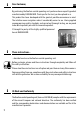
i Dear Customer, EN By purchasing the DuoFern central operating unit you have chosen a quality product manufactured by RADEMACHER. Thank you for the trust you have placed in us. This product has been developed with the greatest possible convenience in mind. The intuitive menu navigation make it considerably easier to use. Having applied uncompromising quality standards, and carried out thorough testing, we are proud to be able to present you with this innovative product.
i Contents Dear Customer,..........................................2 These instructions..... .................................2 CE Mark and Conformity. . ...........................2 Key to symbols..........................................4 General view.............................................5 Functional description...............................6 The „WR ConfigTool“ PC software................7 Functions for DuoFern actuators.................7 Commissioning the central operating unit. . .
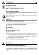
i Key to symbols EN This concerns your safety Please pay particular attention and carefully follow all instructions marked with this symbol. Note / Important / Warning Safety instructions to draw your attention to additional information that is important for trouble-free operation. Please read the operating instructions for the external device (e.g. a DuoFern actuator) described at this point. i Proper use Only use the DuoFern central operating unit ... ...
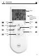
i General view EN Display Battery compartment on the rear side (incl.
i Functional description EN The DuoFern central operating unit is the universal input device for the DuoFern radio system. The DuoFern central operating unit makes it possible to configure the functions you require (e.g. connecting and disconnecting actuators and sensors / creating groups / automatic switching times, etc.) The settings are transmitted wirelessly to all of the actuators and connected end units (appliances). The actuators/sensors must be connected to the central operating unit.
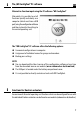
i The „WR ConfigTool“ PC software EN Alternative function input using the PC software "WR ConfigTool" Alternately it is possible to set all functions quickly and clearly on a computer (which must have a USB port) using the configuration software and then to transfer the settings to the central operating unit. The "WR ConfigTool" PC software offers the following options: ◆ ◆ Convenient configuration via computer. ◆ ◆ Assignment of individual names for groups and members. ◆ ◆ Backup your settings.
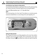
i Commissioning the central operating unit EN Insert batteries (pay attention to the polarity) Insert the batteries into the battery compartment at the rear of the central operating unit. Please pay attention to the correct polarity when inserting the batteries. Only use the following battery type: 3 x 1.5 V type AAA (Micro). Note The central operating unit will not work if the batteries are inserted incorrectly. Incorrectly inserted batteries can cause damage to the central operating unit.
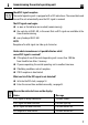
i Commissioning the central operating unit EN Check DCF signal reception The central operating unit is equipped with a DCF radio timer. The current date and time will be set automatically once the DCF signal is received. The DCF signal scan begins: ◆ ◆ as soon as the batteries are inserted (commissioning). ◆ ◆ the next day at 03:01 AM, in the event that no DCF signal was available at the time of commissioning. ◆ ◆ every Sunday at 03:01 AM. Note Reception of a valid signal can take up to 5 minutes.
i The control keys EN The controls keys can be used to navigate within the menus and sub-menus of the central operating unit as well as to carry out all of the required programming settings. The various menu views are described from page 14 on. The following section serves to briefly describe the individual keys and their functions. A precise functional description shall follow in the latter part of this manual, as part of the description for the individual settings.
i Keys OK The control keys EN Description Display Name: OK key Function: a) Open the selected menu. b) Open the selected menu function (e.g. random function). c) Save or confirm the current setting. d) Example Briefly pressing the key causes the status of the current member to be displayed in the normal view. e) Press and hold = toggles between automatic and manual mode in normal view.
i Keys The control keys Description Name: Display Function key Function: a) Switch off manual operation (e.g. end unit) or pause a running roller shutter. b) Different functions depending on the menu, e.g. status display. Symbol: = Name: Group key 12 EN Function: Select a group. Note: No other group can be selected if a point appears next to the number.
i Keys The control keys Description EN Display Name: Member key Function: Select a member from a group. Note: No other member can be selected if a point appears next to the number. Symbol: = Note: The following table describes the relationship between the groups and members view as well as the resulting functions.
i The various menu views EN The respective settings are undertaken in the menus and sub-menus of the DuoFern central operating unit. The menus are grouped according to topics, in order to provide a clearer overview and easier configuration (e.g. manual mode / timer functions / automatic functions / system settings). Note A complete overview of the menus can be found on page 64. Various menu views are used depending on the application (normal mode / main menu settings or system settings).
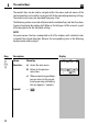
i Keys Normal view EN Description Display Name: Normal view Function: Provides information on: Example - The current date - The current time - The active group - The active actuator - DCF signal - The last received status for the selected group or selected actuator: Automatic switching times Random function Automatic timer Automatic solar function Automatic darkness function Rain function Automatic wind function Note: Th
i Keys Normal view EN Description Display Additional display icons in normal view: - Battery status - Data transfer status Successful data transfer Unsuccessful data transfer - Radio transmission - USB status, the central operating unit is connected to a computer via USB cable.
i The main menu EN From the main menu you can select four sub-menus. Graphical icons are used for these sub-menus to enable easier orientation. As soon as a sub-menu is selected, the border flashes and the name of the menu is shown at the top of the display in the ticker. Key Description Display M Name: Main menu Function: Display and select menus.
i The system settings menu EN The "system settings" menu enables you to undertake all important basic settings (see page 43). All of the sub-menus within the system settings menu are designated with a menu number in order to simplify orientation. The function keys and enable you to quickly select the desired sub-menu and function. Note An overview of the system settings menu is provided on page 65.
i Examples of application EN The easiest way to familiarise yourself with the menu structure and operation of the central operating unit is to carry out the most important tasks for setting up a DuoFern radio network step-by-step. In order to do so, the following pages describe several basic examples: ◆◆ ◆◆ ◆◆ ◆◆ Connecting a DuoFern actuator. Connecting a DuoFern actuator via a radio code. Configuring a switching time for a group. Setting the position of the sun for an end unit (e.g.
i 2 . ,1 Examples of application EN Connecting a DuoFern actuator. Each DuoFern device (actuator/sensor) has to be assigned to the central operating unit in order that your settings and manual switching commands can be executed. In doing so, you can combine the DuoFern actuators into groups. The maximum number of groups and members can be taken from the table on page 6. Name assignment when connecting. An individual name can be assigned to each end unit and group (e.g. lounge, etc.).
i 2 . ,1 Examples of application EN Connecting a DuoFern actuator. Keys 1. Display Activate the actuator's connect mode. Connect mode remains active for approx. 1 minute. Approx. 1 min. 2. Call up the main menu. 3. system Select the " settings menu". 4. Confirm selection. 5. Select the menu "2 radiosettings". 6. Confirm selection. OK 7. Activate function "2 . ,1 Connect". OK M OK The number of connected actuators is indicated on the display (e.g.
i 2 . ,1 EN Examples of application Connecting a DuoFern actuator. Keys 8. The following describes how to connect a new actuator to the central operating unit. 9.a After the connection, select the following for the new actuator: a) a group number b) a member number Note ◆ ◆ Each channel is assigned its own member number for multi-channel actuators, see point 11. ◆ ◆ The central operating unit always suggests the next free member number automatically.
i 2 . ,1 Examples of application EN Connecting a DuoFern actuator. Keys 11. Confirm the name of the new end unit. OK Display a) The following displays can appear: a) Repeat points 9 to 11 for multi channel actuators until all of the actuator channels are assigned.* b) b) For single-channel actuators * 12. * Continue at 13. Confirm the previously assigned name. OK The number of connected actuators is once again indicated on the display. Example 13. Back to normal view.
i 2.2 Examples of application EN Connecting a DuoFern actuator via a radio code. The radio code can be used to directly control DuoFern actuators and connect them to the central operating unit. Once the connection has been successfully established, you can carry out actions such as setting the limit stops for a tubular motor. This offers a huge advantage for operating and configuring flush-mounted devices, as it is not necessary to dismantle them.
i 2.2 Examples of application EN Connecting a DuoFern actuator via a radio code. Keys 1. Select: M 2 2.2 Main menu System settings Radio settings Radio code Display M OK 2. Confirm selection. 3. Enter the six-character radio code of the actuator and confirm each digit. 4. If necessary you can jump back to the previous figure to correct it. 5. Upon confirmation of the last OK figure you can activate ... 6. ...the actuator's connect mode. 7.
i Examples of application EN Configuring switching times for a group You can set individual switching times for each group in order to customise the device to your daily requirements. This example shows you how to configure the switching times for a group to "ALL DAYS SAME, Mo - Su". This setting causes all of the members of the selected group to react at the same configured switching time every day Keys 1. Select: M M Main menu OK Time functions Switching times 2. Confirm selection. 3.
i Examples of application EN Configuring switching times for a group Keys 4. Confirm setting mode. 5. Set the desired switching time "UP (▲)". Display OK OK Setting order: ◆ ◆ Hours ◆ Minutes Optional: ◆ ◆ Hours = OFF Confirm each entry. Note You can also deactivate each switching time UP (▲) / DOWN(▼) if necessary by setting the hours to OFF. 6. Set the desired switching time "DOWN (▼)". OK Confirm each entry. Setting order: ◆ ◆ Hours ◆ Minutes Optional: ◆ ◆ Hours = OFF 7.
i 1. 1. 2. 1 Examples of application EN Setting the position of the sun Note The end points and running time of the roller shutters must be set prior to configuration of the position of the sun(see page 48/46). For end units with automatic solar function, the roller shutters will move to the position of the sun as soon as the solar function is activated. Please additionally read the operating instructions for the corresponding DuoFern actuator. Keys 1. Select: M 1.1 .1 1 . 2 1.1.2.
i 1. 1. 2. 1 Examples of application EN Setting the position of the sun Keys 4. Display Move to the required sun position. The connected tubular motor moves in the corresponding direction. 5. The tubular motor stops as soon as the roller shutters have reached the desired position. Note The position of the sun is displayed as a percentage of the roller shutter's overall travel. 6. Confirm position of the sun. OK The position of the sun is stored on the selected member or end unit. 7.
i Automatic functions in the main menu EN The following section serves to briefly describe the various automatic functions in the main menu as well as their setting parameters. A corresponding menu overview of all automatic functions is included on page 64. It is only possible to carry out these settings if the central operating unit and the corresponding DuoFern actuators are connected to each other and a radio connection has been established between the devices.
M M Menu overview / main menu EN Main menu M Main menu Page Manual mode ...........................................................32 Switching times ...........................................................33 u PROGRAM OFF. . ...................................................34 1 2 3 Time 2 All days same..................................................34 Weekly program.............................................34 Every day different........................................
M Main menu Menu Description Name: EN Display Manual operation Select: M Main menu Manual mode Setting: On = switch on OFF = switch off Function: Toggles between automatic and manual mode. Safety functions such as "wind" are not influenced by manual mode. NOTE: You can also toggle between automatic and manual modes in the normal view. 1. / Select the desired device. 2. OK approx. 2 sec. Automatic operation Press and hold the key until the smiley icon is displayed.
M Main menu Menu Description Name: Select: EN Display Switching times M Main menu Time functions Switching times Setting: ◆ PROGRAM OFF 1 ALL DAYS SAME 2 WEEKLY PROGRAM 3 EVERY DAY DIFFERENT Function: ◆ Automation of roller shutters and additional switch actuators: – Opening and closing times for roller shutters. – On and off times for additional end units. – Set individual switching times per group. ◆ Configure a second switching time per group.
M Main menu Menu Description EN Display Name: PROGRAM OFF All switching times are deactivated. No additional settings can be undertaken for the following functions. Name: 1 ALL DAYS SAME Setting: 1 x UP/DOWN The same switching times for every day of the week from Monday to Sunday.
M Main menu Menu Description EN Display Configure a second switching time. Note If the "2nd switching time [1 . 2 . 3 ]" function is activated (see page 51), it is possible to configure a second switching time for all previously described switching times. The respective switching time (Time 1/ Time 2) is shown as a ticker and left-hand digit. 1. Switching time " 1 ALL DAYS SAME" Call up the first or second switching time (Time 1/ Time 2) and automatic timer. 1. Open the switching times menu. * 2.
M Main menu Menu Description EN Display Name: Random function Select: M Main menu Time functions Random Function: This function causes a random delay to the configured switching time between 0 and 30 minutes for the selected actuator. Further important information: Menu Description Display Name: Automatic timer Select: M Main menu Automatic functions Time Function: Further important information: 36 Switch the automatic timer for the selected actuator on / off.
M Main menu Menu Description EN Display Name: Automatic solar function Select: M Main menu Automatic functions Sun Function: Switch the automatic solar function for the selected actuator on / off. Note You can only activate the automatic solar function if the position of the sun has previously been configured for the actuator. Please also observe the application example beginning on page 28.
M Menu EN Description Main menu Name: Display Dawn / Dusk HINWEIS Astro function: The time of the switching command depends on the date and the geographical location of your installation. The settings in menu " 1 . 3 . 2 ASTRO" must be checked (see page 54) in order to ensure that the Astro function operates correctly.
M Main menu Menu Description EN Display Important The following applies to actuators which are connected in numerous groups: You can only assign one switching command for dawn and dusk per actuator. Further important information: Configure the desired function. Name: u Automatic Function: Switch the automatic darkness function on/off for the actuator. Name: u Customise Function: Change the switching time for the automatic darkness function by +/- 60 minutes (increment = 10 minutes).
M Main menu Menu Description EN Display Name: u Earliest / latest Function: u Earliest – Dawn is not executed before this time. u Latest – Dusk is executed at this time, at the latest. Name: u On days Setting: 1 2 3 4 MON - SUN MON - SUN SAT SUN MON TUES WED THUR FRI SAT SUN Function: Dusk/dawn is executed on the selected days: 1 MON - SUN Every day of the week 2 MON - SUN Monday to Friday. 3 SAT SUN Saturday and Sunday.
M Main menu Menu Description Name: Function: EN Display u Execute Once the automatic darkness function has been configured, the switching times for the dawn / dusk automatic darkness function are shown for the current day.
M Main menu Menu Description EN Display Name: Rain function Select: M Main menu Automatic functions Rain Function: Switch the rain function for the selected actuator on / off. Further important information: Menu Description Display Name: Automatic wind function Select: M Main menu Automatic functions Wind Function: Further important information: 42 Switch the automatic wind function for the selected actuator on/off.
System settings EN The following section serves to briefly describe the various system settings and their parameters. A brief menu overview of the menus is included on page 64. The structure of the sub-menus is presented to you in the corresponding chapter, for example, page 44. Please check to see whether your actuator supports the desired function. Note The previous chapters explained in detail how to navigate through the individual menus.
Menu overview / 1. 1 Actuators EN System settings 1 Basic settings Page 1. 1 1.2 1.3 1.4 * Actuators 1. 1.1 1.1.2 Name ...........................................................44 ...........................................................45 Special functions * 1 . 1 . 2 . 1 Position of the sun...............................45 1 . 1 . 2 . 2 Ventilation / intermediate position.......45 1 . 1 . 2 . 3 Remote log-on / log-off 1 . 1 . 2 . 4 Stairway / impulse function..................46 1 . 1 .
Menu overview / 1.1 Actuators Menu Description 1. 1.1 Name: Name Function: EN Enter a name for the current actuator. A table with the default suggested names is included on page 63. Note You can customise the names using the WR ConfigTool software. Menu Description 1. 1.2.1 Name: Sun position Function: Setting the position of the sun for the current actuator. For key function and order, see page 28. Menu Description 1. 1.2.
Menu overview / Menu 1. 1.2.3 1. 1 Actuators EN Description Name: Remote log on / off Function: Activate connect / disconnect mode for an actuator. Subsequently, you can connect a DuoFern flush-mounted actuator with another DuoFern manual transmitter, for example. Connect Quit connect / disconnect mode Disconnect Menu Description 1. 1.2.4 Name: Stairway / impulse function Function: Switch the stairway / impulse function on / off for the selected actuator.
Menu overview / 1.1 Actuators EN Menu Description 1. 1.2.6 Name: Change direction of rotation / function Function: Reverse the direction of rotation for an actuator to control roller shutters or Change the function of an actuator. Menu Description 1. 1.2.7 Name: Wind direction of travel Function: Set the direction of travel for an actuator in the event that "wind" is detected for an active automatic wind function. Menu 1. 1.2.
Menu overview / 1.1 Actuators EN Menu Description 1. 1.2.A Name: End points Function: Set the upper and lower end point for the currently selected drive. Proceed as follows: 1. / Move the roller shutters to the centre position. 2. Call up the menu " 1 . 1 . 2 . A ". 3. / Press and hold the required key; the roller shutter moves up or down.. 4. Release the button as soon as the desired end point is reached.
Menu overview / 1.2 Groups EN System settings 1 Basic settings Page 1. 1 1.2 1.3 1.4 Actuators ( 1 . 1 . 1 - 1 . 1 . 2 ).....................................................44 Groups ( 1 . 2 . 1 - 1 . 2 . 4 ). . ....................................................49 1.2.1 1.2.2 1.2.3 1.2.4 Name ...........................................................50 Member ...........................................................50 2nd switching time.............................................
Menu overview / 1.2 Groups Menu Description 1.2.1 Name: Name Function: EN Select a name for the current group. A table with the default suggested names is included on page 63. Additional configuration options are available with the "WR ConfigTool" software. Menu Description 1.2.2 Name: Members Function: Assign a connected DuoFern actuator as a member of a group. Note ◆ The actuator may not already be a member of this group.
Menu overview / 1.2 Groups EN Menu Description 1.2.3 Name: 2nd switching time Function: Switch the second switching time for a group on / off. Instructions on how to configure a second switching time are given on page 35. Menu Description 1.2.4 Name: Venetian blinds function / jog mode Function: If jog mode is active, a corresponding movement command is transmitted in normal mode by briefly pressing " or ". The drive moves gradually in the desired direction.
Menu overview / 1.3 Central operating unit System settings 1 Basic settings Page 1. 1 1.2 1.3 1.4 52 Actuators ( 1 . 1 . 1 - 1 . 1 . 2 ).....................................................44 Groups ( 1 . 2 . 1 - 1 . 2 . 4 ). . ....................................................49 Central operating unit ( 1 . 3 . 1 - 1 . 3 . 7 )................................52 1.3.1 Time 1.3.1.1 1.3.1.2 1.3.1.3 1.3.1.4 Settings. . .............................................53 DCF clock.....................
Menu overview / 1.3 Central operating unit EN Menu Description 1.3.1.1 Name: Settings (time) Function: Manual settings for time and date. The setting is undertaken automatically one after the other. Note This function is only accessible if: ◆ No DCF signal has been received. ◆ DCF reception is deactivated. ◆ Directly after inserting the batteries. Menu 1.3.1.2 Description Name: DCF clock Function: Switch DCF signal reception on/off.
Menu overview / 1.3 Central operating unit Menu Description 1.3.1.4 Name: SU-WI time Function: Switches automatic daylight saving time switch-over on / off. EN Proceed as follows to activate automatic switch-over: 1. Activate Su-Wi switch-over. 2. Set the desired broadcasting time. Note If you set a broadcasting time prior to the actual switch-over, the new time will be broadcast immediately once the switch-over is reached. Menu Description 1.3.2.
Menu overview / Menu 1.3.2.2 1.3.2.3 EN Description Name: Astro times Function: Menu 1.3 Central operating unit Enables you to view the calculated twilight times for the selected postcode. Description Name: Twilight Function: Switches the twilight time calculation function on / off on the central operating unit. Menu Description 1.3.3 Name: Key lock Function: Activate / deactivate key lock or menu lock. This enables you to prevent unintentional operation of the central operating unit.
Menu overview / 1.3 Central operating unit Menu Description 1.3.4 Name: Contrast Function: Enables the display contract to be set. 1 5 low contrast high contrast Menu Description 1.3.5 Name: Ticker Function: Setting the ticker speed. 1 8 slow fast Menu Description 1.3.6 Name: Language Function: Set the desired language. 1 2 3 4 5 German English Spanish French Dutch Menu Description 1.3.
Menu overview / 1.4 Sensors EN System settings 1 Basic settings Page 1. 1 1.2 1.3 1.4 Actuators ( 1 . 1 . 1 - 1 . 1 . 2 ). . ..................................................44 Groups ( 1 . 2 . 1 - 1 . 2 . 4 ). . ....................................................49 Central operating unit ( 1 . 3 . 1 - 1 . 3 . 7 )................................52 Sensors ( 1 . 4 . 1 - 1 . 4 . d ).....................................................57 1.4.1 1.4.2 1.4.3 1.4.4 1.4.5 1.4.6 1.4.7 1.4.8 1.4.9 1. 4.
Menu overview / 2 Radio settings EN System settings 2 Radio settings Page 2. 1 2.2 2.3 Connect/disconnect.........................................................58 Radio code ...........................................................59 Clear ...........................................................59 Menu Description 2.1 Name: Connect / disconnect Function: Connect a DuoFern actuator to the central operating unit or disconnect from the central operating unit.
Menu overview / 2 Radio settings Menu Description 2.2 Name: Radio code Function: EN Switches a DuoFern device to connect or disconnect mode with the radio code (see application example on page 24). Connect Quit connect / disconnect mode Disconnect Note For security reasons, this function is only available for the first two hours after switching on the power supply. Further important information: Menu Description 2.
TD TD Technical Specifications EN Supply voltage: 4.5 V Battery type: 3 x 1.5 V type AAA (micro) Battery life: approx. 2 years Transmission frequency: 434.5 MHz Transmission power: 10 mW Range: 100 m (outdoors) Clock: DCF radio timer DCF reception (range): approx. 1500 km from Frankfurt am Main / Germany Max. number of groups: 9 Max. number of members per group: 9 Number of end units: 81 (total) Ambient conditions: Device may only be used in dry rooms.
i Time zone table Germany 0 - 99 postcode Belgium 100 Arlon 101 Antwerp 102 Bruges 103 Brussels 104 Liège 105 Mechelen 106 Mons 107 Ostend Denmark 108 Aalborg 109 Ringsted 110 Esbjerg 111 Horsens 112 Kolding 113 Copenhagen 114 Svendborg 115 Randers England 116 Aberdeen 117 Birmingham 118 Bristol 119 Glasgow 120 London 121 Manchester 122 Newcastle Estonia 123 Tallinn Finland 124 Helsinki 125 Jyyäskylä 126 Oulu EN 127 Tampere 128 Turku 129 Vasa France 130 Bordeaux 131 Brest 132 Dijon 133 Le Havre 134 Lyon 1
i Time zone table Poland Spain 184 Wrocław 185 Bromberg 186 Danzig 187 Kattowitz 188 Krakow 189 Lodz 190 Lublin 191 Posen 192 Stettin 193 Warsaw Portugal 214 215 216 217 218 219 220 221 222 223 224 225 226 227 228 229 230 231 232 233 234 235 236 237 238 239 240 241 242 194 Faro 195 Lisbon 196 Porto Switzerland 197 Basel 198 Bern 199 Andermatt 200 Chur 201 Lausanne 202 Lucerne 203 Zurich Sweden 204 205 206 207 208 209 210 211 212 213 62 EN Boras Gävle Gothenburg Helsingborg Jönköping Östersund Malmö S
i Suggested names for groups and members EN No. Name No.
i Menu overview EN Normal view (example) Main menu Manual operation Time functions Switching times Random Automatic functions Time Sun Twilight Rain Wind System settings (see next page) 1 2 64 Basic settings ( 1 . 1 - 1 . 4 ) Radio settings ( 2 . 1 - 2 .
i Menu overview EN System settings 1 2 Basic settings Page 1. 1 1.2 1.3 1.4 Actuators ( 1 . 1 . 1 - 1 . 1 . 2 )......................................44 Groups ( 1 . 2 . 1 - 1 . 2 . 4 ). . .....................................49 Central operating unit ( 1 . 3 . 1 - 1 . 3 . 7 ).................52 Sensors ( 1 . 4 . 1 - 1 . 4 . d ) .....................................57 Radio settings Page 2. 1 2.2 2.3 Connect/disconnect.......................................... 58 Radio code......................
i CE Mark and EC Conformity EN The present product complies with the requirements of the current European and national directives. 1999/5/EC R&TTE directive Conformity has been verified. The corresponding declarations and documentation are available on file at the manufacturer’s premises. RADEMACHER Geräte-Elektronik GmbH & Co.
i Warranty conditions EN RADEMACHER Geräte-Elektronik GmbH & Co. KG provides a 24-month warranty for new systems that have been installed in compliance with the installation instructions. All construction faults, material defects and manufacturing defects are covered by the warranty.
Service: Hotline 01807 933-171* Fax +49 2872 933-253 service@rademacher.de * 30 seconds free of charge, subsequently 14 cents / minute from German fixed line networks and max. 42 cents / minute from German cellular networks. Subject to technical modifications, misprints and errors. Illustrations not binding. raDEMaCHEr Geräte-Elektronik GmbH & Co. KG Buschkamp 7 46414 Rhede (Germany) info@rademacher.de www.rademacher.