
Specifications

IPmux-4 Installation and Operation Manual Appendix E Parameters and Screens
E1/T1 Configuration Parameters E-15
IPmux-4-4E1/4T1
Only
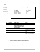
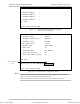
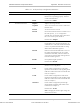
CHANNEL NUMBER CONFIGURATION
1. Channel number 1 >
2. Channel number 2 >
3. Channel number 3 >
4. Channel number 4 >
ESC. Exit
Select item from the menu.
Figure E-18. Channel Number Configuration Window
(For versions with 4 ports)
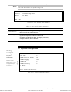
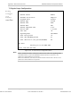
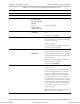
PHYSICAL LAYER CONFIGURATION
1. Channel Status Enable
2 Transmit Clock Source Adaptive
3. Loopback State Disable
4. Rx. Sensitivity -10dB
5. Channel Type CRC4 Enable
6. Idle Code 7E
7. Signaling Mode CAS Enable
8. Cond. Data pattern FF
9. Cond. CAS (ABCD) pattern 01
ESC. Exit
Current port is the USER PORT, Channel #1
Select item from the menu.
Figure E-19. E1 Physical Layer Configuration Menu
When “unframed” mode is selected, the Idle Code, Signaling Mode, Cond Data
Pattern and Cond CAS Pattern fields are not present.
When CAS Disabled is selected, the Cond CAS Pattern field is not present.
Note
Order from: Cutter Networks
Ph:727-398-5252/Fax:727-397-9610
www.bestdatasource.com