
Specifications


Appendix E Parameters and Screens IPmux-4 Installation and Operation Manual
E-8 General Configuration
➤
To ping the manager
• Press P.
➤
To access additional manager-list parameters,
• Press N to go to the next manager-list window.
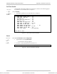
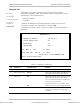
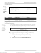
Alarms Trap Mask
Alarms Trap Mask
1. Alarm ID 1
2. Trap Status Active
ESC. Exit S. save
ACTIVE ALARM TRAPS: 1, 2, 6, 8
Figure E-10. Alarms Trap Mask Window
Each of the IPmux-4 alarms can activate a trap toward the NMS. It is possible to
enable/disable the trap operation for each one of the alarms, using the Alarm Trap
Mask screen.
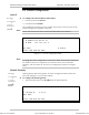
Table E-3. Alarms Trap Parameters
Key Parameter Possible Values Remarks
1 Alarm ID
1 – 40
See Table E-4
2 Trap Status
Active
Masked
Generates a trap
No alarms are sent
Default: Masked
Table E-4. IPmux-4 Alarms
Alarm ID Alarm Description Trap Sent to NMS
1 Loss of Signal (LOS Physical Layer) Alarm LOS
1.3.6.1.4.1.164.6.1.3.0.7
2 Loss of Frame (LOF Physical Layer) Alarm LOF
1.3.6.1.4.1.164.6.1.3.0.8
6 Alarm Indication Signal Received (AIS Line
Physical Layer)
Alarm AIS
1.3.6.1.4.1.164.6.1.3.0.10
8 Remote Defect Indication Received (RDI Line
Physical Layer)
Alarm RDI
1.3.6.1.4.1.164.6.1.3.0.11
21 Far End Block Error (FEBE Line Layer) Alarm FEBE
1.3.6.1.4.1.164.6.1.3.0.12
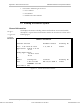
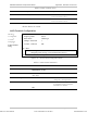
Main menu
↓
2. Configuration
↓
1. General Configuration
↓
3. Management
Configuration
↓
3. Alarms Trap Mask
Order from: Cutter Networks
Ph:727-398-5252/Fax:727-397-9610
www.bestdatasource.com