
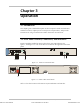
Specifications


Chapter 3 Operation IPmux-4 Installation and Operation Manual
3-2 Operating Instructions
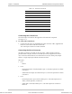
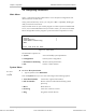
Table 3-1. IPmux-4 System Indicators and Switches
No Module Name Type Function
1 System RDY LED On: Device OK
OFF: Self-test in progress
Blinking: Malfunction detected
2 System PS1/PS2 LED On: Unit powered
Off: Unit not powered
3 Ethernet LINK LED Off: Link not active
On: Line OK
4 Ethernet ACT LED Off: No activity
On: Frame being transferred on line
5 Ethernet 100M LED Off: 10 MHz
On: 100 MHz
6 Ethernet FDX LED Off: Half duplex
On: Full duplex
7 E1 SYNC LED On: Port synchronized (no alarm)
Off: Unframed - Signal loss or AIS
detected
Framed - Signal loss, loss of frame or
AIS detected
Blinking: RDI detected (remote alarm)
8 Rear panel PS1/PS2 Switch Turns IPmux-4 power On and Off
3.3 Operating Instructions
Turning IPmux-4 On – Without Control Terminal
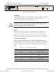
IPmux-4 power switches are located on the back panel, as shown in Figure 3-2.
➤
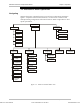
To power up IPmux-4 without a terminal:
• Switch the PS1 power supply switch, located on the rear panel, to ON.
IPmux-4 can be optionally equipped with a second power supply (PS2). If
present, switch PS2 to ON.
After power-up, check the unit LED indicators, located on the right side of the
front panel, and the module indicators for proper operation (see Figure 3-1,
Figure 3-2, and Table 3-1).
Order from: Cutter Networks
Ph:727-398-5252/Fax:727-397-9610
www.bestdatasource.com