
Specifications


Front Panel Controls, Connectors, and Indicators 3-1
Chapter 3
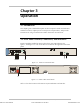
Operation
3.1 Introduction
This chapter gives a detailed description of the front panel controls and indicators
and their functions, explains power-on and power-off procedures, and provides
instructions for using a terminal connected to the IPmux-4 Control Port.
3.2 Front Panel Controls, Connectors, and Indicators
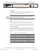
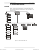
Interface modules installed in IPmux-4 have their own LED indicators (see
Figure 3-1and Figure 3-2). The unit's LEDs are located on the right side of the front
panel.
ETH/FC13L/E3
-
CES
RXTX
SYNC
ETHETH
ETH/4E1
SYNC
100MLINK
FDXACT
1 2
3 4 5 6 7
12
34
CH4
CH1
Figure 3-1. IPmux-4 Front Panel LEDs
ALARMS
PS1
POWER
PS1
O
I
8
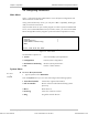
Figure 3-2. IPmux-4 Rear Panel Switch
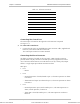
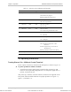
Table 3-1 lists the functions of the IPmux-4 system indicators and switches.
Order from: Cutter Networks
Ph:727-398-5252/Fax:727-397-9610
www.bestdatasource.com