
Specifications

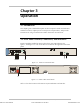


IPmux-4 Installation and Operation Manual Chapter 2 Installation
Installation and Setup 2-7
The DB-9 connector also allows alarms to be sent to the NMS (Input alarms).
These alarms are called General Alarms and are numbered 1 through 4.
• Pin 1 (shorted to pin 8) sends NMS General Alarm 1
• Pin 2 (shorted to pin 8) sends NMS General Alarm 2
• Pin 7 (shorted to pin 8) sends NMS General Alarm 3
• Pin 8 (shorted to pin 8) sends NMS General Alarm 4.
The alarms that trigger the relay are listed in Chapter 3, Table 3-1. The relay will be
activated only if the specific Alarm trap is enabled (not masked).
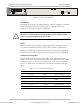
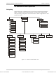
Connecting the Power
IPmux-4 is available with either an AC or a DC power supply (Figure 2-2).
➤
To connect the power:
1. Connect the power cord, supplied with IPmux-4, to PS1 on the IPmux-4 rear
panel. If a redundant power supply is present, connect the ther power cord
supplied to PS2.
2. Before connecting IPmux-4 to power, check that the ON/OFF switch(es) on
the rear panel is (are) set to OFF.
3. Connect the power cord first to PS1 (and PS2) and then to the mains outlet.
The outlet should be within 1.5 meters (five feet) of the unit.
The power cord must be plugged into an outlet with a protective ground (earth)
contact. The protective action must not be negated by use of an extension cord
without a protective conductor (grounding).
Caution
Order from: Cutter Networks
Ph:727-398-5252/Fax:727-397-9610
www.bestdatasource.com