
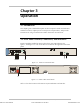
Specifications


Chapter 2 Installation IPmux-4 Installation and Operation Manual
2-6 Installation and Setup
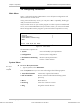
Table 2-4. Ethernet Port Pinout
Pin # Pinout
1 Tx+
2 Tx–
3 Rx+
4
5
6 Rx–
7
8
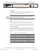
Connecting the Control Port
The Control port is located on the right side of the IPmux-4 front panel
(see Figure 2-3).
➤
To connect the Control Port:
• Connect the RS-232/V.24, shielded RJ-45 DTE connector cable, supplied with
IPmux-4, to the IPmux and then to the DTE.
The control port is DTE for an ASCII terminal.
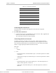
Connecting the Alarm Connector
An Alarms connector is located on the rear panel. A DB-9 female connector
provides alarm relay dry-contacts to external supervisory equipment (for future
use). This feature allows IPmux-4 to send alarms on its dry contact port (Output
alarms). A single output pin indicates an IPmux-4 alarm.
DB-9 pins:
• Pin 3
− INPUT
• Pin 4
− Normal Operation: Closed (shorted to pin 3). This state represents no alarm
in IPmux-4.
− Alarm Detected: Open (not shorted to pin 3). This state represents an alarm
in IPmux-4.
• Pin 5
− Normal Operation: Open (not shorted to pin 3). This state represents no
alarm, normal operation, in IPmux-4.
− Alarm State: Closed (shorted to pin 3). This state represents an alarm in
IPmux-4.
Order from: Cutter Networks
Ph:727-398-5252/Fax:727-397-9610
www.bestdatasource.com