
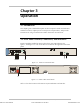
Specifications


IPmux-4 Installation and Operation Manual Chapter 2 Installation
Installation and Setup 2-5
ETH/FC13L/E3-CES
RXTX
SYNC
ET HET H
ETH / 4E1
SYNC
100MLINK
FDXACT
12
34
CH 4
CH 1
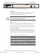
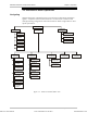
Figure 2-3. IPmux-4 Front Panel
Grounding
Interrupting the protective grounding conductor (inside or outside the instrument)
or disconnecting the protective earth terminal can make this instrument
dangerous. Intentional interruption is prohibited.
Before switching ON this instrument and before connecting any other cable,
the protective earth terminals of this instrument must be connected to the
protective ground conductor of the power cord.
Fuses
Make sure that only fuses with the required rated current and specified type,
2 A T 250V as marked on the IPmux-4 rear panel, are used for replacement.
Whenever it is likely that the protection offered by fuses has been impaired, the
instrument must be made inoperative and be secured to prevent any operation.
Location of Connectors
Connect the E1/T1 and Ethernet ports according to the appropriate pinout.
Interface connections are made from the IPmux-4 front panel from each module,
as shown in Figure 2-3. The connectors required for each interface are listed in
Section 2.4, above. E1/T1 and Ethernet port pinouts are listed in the following
tables.
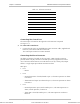
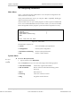
Table 2-3. E1/T1 Port Connectors Pinout
Pin Designation Direction Function
1 RD (R) Input Receive data (ring)
2 RD (T) Input Receive data (tip)
3,6 – – FGND
4 TD (R) Output Transmit data (ring)
5 TD (T) Output Transmit data (tip)
7,8 – N/A Not connected
Warning
Order from: Cutter Networks
Ph:727-398-5252/Fax:727-397-9610
www.bestdatasource.com