
Specifications

Chapter 2 Installation IPmux-4 Installation and Operation Manual
2-4 Installation and Setup
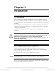
1
2
3
4
5
6
7
8
1
2
3
4
5
6
7
8
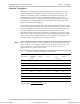
RJ-45
DB-9
CBL-RJ-45/DB9/NULL
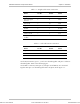
Figure 2-1. Null Cable (CBL-RJ-45/DB-9/Null) Pin Shorts
2.5 Installation and Setup
Setting Jumpers
IPmux-4 internal jumpers and switches do not need to be configured by the user
and therefore removing the product cover is not required.
Connecting Interfaces and Cables
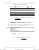
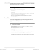
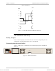
Figure 2-2 and Figure 2-3 illustrate the rear and front panel options available for
IPmux-4.
ALARMS
PS1
POWER
PS1
O
I
Figure 2-2. IPmux-4 Rear Panel
Order from: Cutter Networks
Ph:727-398-5252/Fax:727-397-9610
www.bestdatasource.com