
Specifications

IPmux-4 Installation and Operation Manual Chapter 2 Installation
Equipment Needed 2-3
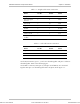
Table 2-1. Straight Cable Pinout Connections
EIA/TIA-561
Name
EIA/TIA-561
Pin No.
DB-25 Male
Pin No.
EIA 232
Name
Ring Indicator 1 6 DSR
RCV Line Signal
Detector
2 8 DCD
DTE Ready 3 20 DTR
Signal Common 4 7 Common
Rx data 5 3 Rx data
Tx data 6 2 Tx data
Clear To Send 7 5 CTS
Req To Send/Ready
for RCV
8 4 RTS
Table 2-2. Null Cable Pinout Connections
EIA/TIA-561
Name
EIA/TIA-561
Pin No.
DB-9 Male
Pin No.
EIA 232
Name
Signal Common 4 5 Common
Rx data 5 3 Rx data
Tx data 6 2 Tx data
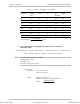
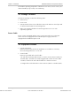
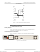
On the RJ-45connector, pins 1, 2, and 3 are shorted together and pins 7 and 8 are
shorted together. Refer to the following figure.
On the DB-9 connector, DCD (pin 1), DTR (pin 4) and DSR (6) are connected
together. RTS (pin 7) is shorted together with CTS (pin 8). Refer Figure 2-1.
Order from: Cutter Networks
Ph:727-398-5252/Fax:727-397-9610
www.bestdatasource.com