
Specifications

IPmux-4 Installation and Operation Manual Chapter 1 Introduction
Functional Description 1-9
IP over
Ethernet
Loopback
Timing
E1/T1
External Clock
E1/T1
GPS
Clock Source
GPS
Clock Source
Loopback
Timing
External Clock
IPmux-4
IPmux-4
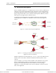
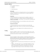
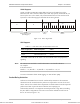
Figure 1-7. IPmux-4 in External Timing Mode
Single Clock Source Network
In this mode, the central site serves as the clock source for the whole network.
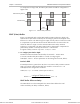
When bundles from several sources arrive at the same E1/T1 port, the clock is
regenerated from the first bundle of each port (for E1, bundle number 1 for port 1,
bundle number 32 for port 2, bundle number 63 for port 3, bundle number 94 for
port 4).
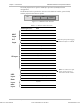
Multiple sites that are transmitting to an IPmux-4 port that is set to adaptive mode
must have the same source clock. The following table describes configuration
options:
Table 1-1. Adaptive (Master) Clock Configuration Options
Central Site IPmux-4 Clock
Configuration
Remote Site IPmux-4 Clock
Configuration
INT Adaptive
LBT Adaptive
EXT Adaptive
IPmux-4
E1/T1
E1/T1
IPmux-4
E1/T1
E1/T1
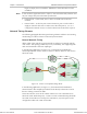
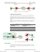
Adaptive Mode
Loopback Timing Mode
IPmux-4
E1/T1
E1/T1
Adaptive Mode
Master Clock
Source Device
Remote Loopback
Timing Devices
IP over
Ethernet
Figure 1-8. IPmux-4 in Adaptive Timing Mode
Frame Format
The Ethernet frame sent by the IPmux-4 is a UDP datagram that transfers E1/T1
payload bytes over IP over Ethernet (UDP payload + UDP header + IP header +
Ethernet header).
Order from: Cutter Networks
Ph:727-398-5252/Fax:727-397-9610
www.bestdatasource.com