
Specifications

Chapter 1 Introduction IPmux-4 Installation and Operation Manual
1-8 Functional Description
begins to empty, the Tx (toward the TDM device) clock decreases to avoid
underflow.
In this mode the regenerated clock is subject to network Packet Delay Variation and
may not comply with jitter and wander specifications.
• Internal Clock – in this mode, the Tx clock is received from an internal
oscillator.
• External Clock – in the four-port version of IPmux-4, port 4 can be used to
supply an external clock source. When one of the other ports (1, 2 or 3) is
configured to external clock, its Tx clock is taken from the Rx clock of port 4.
Network Timing Schemes
The following paragraphs describe typical timing schemes and their correct timing
mode settings in order to achieve end-to-end synchronization.
External Network Timing
All the edges of the network are synchronized according to an external network
clock source. This topology enables any-to-any connectivity, thus supporting both
mesh and star bundle connection topologies.
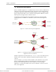
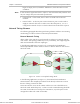
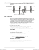
In the following application (see Figure 1-6), an External Clock Distribution
Network provides the clock to the E1/T1 devices. All three IPmux-4 units work in
LBT clock mode.
IP over
Ethernet
E1/T1 Device
E1/T1
E1/T1
E1/T1 Device
E1/T1
E1/T1
E1/T1 Device
E1/T1
E1/T1
Clock from
External
Distribution
Network
IPmux-4
IPmux-4
IPmux-4
Figure 1-6. IPmux-4 in Loopback Timing Mode
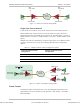
In the following application (see Figure 1-7), the External Clock Distribution
Network (GPS in this example) provides the clock directly to the IPmux-4 units
that are working in EXT clock mode.
Port 4’s Rx interface serves as the “Station Clock Port”. Port 4 should be set to
LBT clock mode. While the port (1–3) that is to work in External timing should be
set to EXT clock mode (since each port is autonomous, any of the ports can be
configured to either LBT or EXT clock mode).
Note
Order from: Cutter Networks
Ph:727-398-5252/Fax:727-397-9610
www.bestdatasource.com