
- RAD Data Communications TDMoIP Gateway Installation and Operation Manual
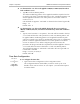

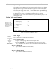
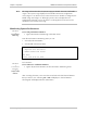
Table Of Contents
- Contents
- Introduction
- Installation
- Operation
- Introduction
- Front Panel Controls, Connectors, and Indicators
- Operating Instructions
- Getting Started
- Menu Operations
- Configuring System Parameters
- Configuring IPmux-16
- Troubleshooting and Diagnostics
- Boot Sequence for Downloading Software
- SNMP Management
- Telnet
- TFTP Download Procedures
- DC Power Supply Connection – CBL-DC-3WL/F

IPmux-16 Installation and Operation Manual Chapter 3 Operation
Configuring IPmux-16 3-29
T1 Physical Layer Configuration
T1 PHYSICAL LAYER CONFIGURATION
1. Transmit Clock Source Adaptive
2. Loopback State Disable
3. Channel Type T1-ESF
4. Channel Code B8ZS
5. Channel Mode DSU
6. Channel Length/Tx Gain 0-133
7. Restore Time 1 second
8. Idle Code 7E
9. Signaling Mode CAS enable
A. Cond. Data pattern 7F
B. Cond. CAS (AB/ABCD) pattern 01
C. Cond. CAS first 2.5sec pattern(FF=NULL) FF
ESC. Exit
Current port is the USER PORT
Select item from the menu.
Figure 3-30. T1 Physical Layer Configuration Menu
When “unframed” mode is selected, the Restore Time, Idle Code, Signaling Mode,
Cond Data Pattern, Cond CAS (AB/ABCD) Pattern and Cond. CAS first 2.5sec
pattern (FF=NULL) fields are not present.
When CAS Disabled is selected, the Cond CAS Pattern and Cond. CAS first 2.5sec
pattern (FF=NULL) fields are not present.
➤
To change the source of the transmit clock:
• Type 1 and press the spacebar on your keyboard to toggle between
Adaptive/Loopback/Internal/External
Adaptive: Adaptive clock regeneration
Loopback: T1 recovered receive clock used as the transmit clock
Internal: Local clock source used
Default value: Adaptive
Note