
- RAD Data Communications TDMoIP Gateway Installation and Operation Manual
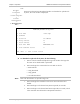
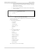
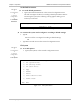
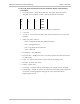
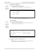
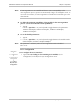
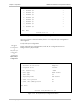
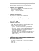
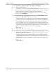
Table Of Contents
- Contents
- Introduction
- Installation
- Operation
- Introduction
- Front Panel Controls, Connectors, and Indicators
- Operating Instructions
- Getting Started
- Menu Operations
- Configuring System Parameters
- Configuring IPmux-16
- Troubleshooting and Diagnostics
- Boot Sequence for Downloading Software
- SNMP Management
- Telnet
- TFTP Download Procedures
- DC Power Supply Connection – CBL-DC-3WL/F

Chapter 3 Operation IPmux-16 Installation and Operation Manual
3-26 Configuring IPmux-16
E1/T1 PHYSICAL LAYER CONFIGURATION
1. Channel #1 >
2. Channel #2 >
3. Channel #3 >
4. Channel #4 >
5. Channel #5 >
6. Channel #6 >
7. Channel #7 >
8. Channel #8 >
ESC. Exit
Current Slot is 3
Figure 3-28. E1/T1 Physical Layer Configuration Menu
Once you choose a channel number, the E1 or T1 Physical Layer Configuration
menu appears.
E1 Physical Layer Configuration
Main Menu
↓
2. Configuration
↓
2. Physical Layer
Configuration
↓
3 or 4. E1/T1
Physical Layer
Configuration
Type 1 (Physical Layer Configuration) in the E1/T1 Configuration menu to
configure the E1 physical layer.
PHYSICAL LAYER CONFIGURATION
1. Transmit Clock Source Adaptive
2. Loopback State Disable
3. Rx. Sensitivity -10dB
4. Line Type CRC4 enable
5. Idle Code 7E
6. Signaling Mode CAS enable
7. Cond. Data pattern FF
8. Cond. CAS (ABCD)pattern 01
ESC. Exit
Current Slot/Channel is 3/1
Figure 3-29. E1 Physical Layer Configuration Menu