
- RAD Data Communications TDMoIP Gateway Installation and Operation Manual
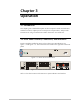
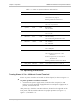
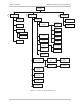
Table Of Contents
- Contents
- Introduction
- Installation
- Operation
- Introduction
- Front Panel Controls, Connectors, and Indicators
- Operating Instructions
- Getting Started
- Menu Operations
- Configuring System Parameters
- Configuring IPmux-16
- Troubleshooting and Diagnostics
- Boot Sequence for Downloading Software
- SNMP Management
- Telnet
- TFTP Download Procedures
- DC Power Supply Connection – CBL-DC-3WL/F
Front Panel Controls, Connectors, and Indicators 3-1
Chapter 3
Operation
3.1 Introduction
This chapter gives a detailed description of the front panel controls and indicators
and their functions, explains power-on and power-off procedures, and provides
instructions for using a terminal connected to the IPmux-16 Control Port.
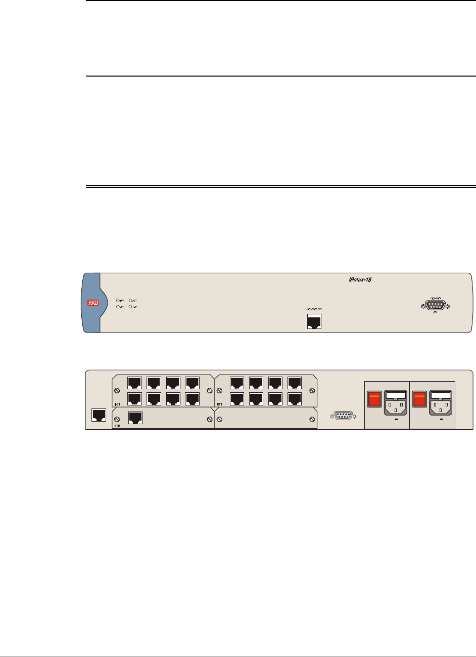
3.2 Front Panel Controls, Connectors, and Indicators
Interface modules installed in IPmux-16 have their own LED indicators (see
Figure 3-1 and Figure 3-2). The unit's LEDs are located on the right side of the front
panel.
Figure 3-1. IPmux-16 Front Panel LEDs
PS2
PS1
~100 -24 0VAC 3A T 1 25V~100 -24 0VAC 3A T 125V
AL ARMS
POWERPOWER
O
O
I
I
EXT. CLK
Figure 3-2. IPmux-16 Rear Panel Switch
Table 3-1 lists the functions of the IPmux-16 system indicators and switches.