
- RAD Data Communications TDMoIP Gateway Installation and Operation Manual
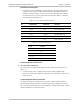
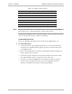
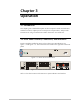
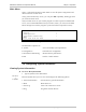
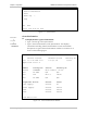
Table Of Contents
- Contents
- Introduction
- Installation
- Operation
- Introduction
- Front Panel Controls, Connectors, and Indicators
- Operating Instructions
- Getting Started
- Menu Operations
- Configuring System Parameters
- Configuring IPmux-16
- Troubleshooting and Diagnostics
- Boot Sequence for Downloading Software
- SNMP Management
- Telnet
- TFTP Download Procedures
- DC Power Supply Connection – CBL-DC-3WL/F
IPmux-16 Installation and Operation Manual Chapter 2 Installation
Installation and Setup 2-5
Location of Connectors
• Connect the E1/T1 and Ethernet ports according to the appropriate pinout.
Interface connections are made from the IPmux-16 front panel from each
module, as shown in Figure 2-3. The connectors required for each interface
are listed in Section 2.4. E1/T1 port pinouts are listed in Table 2-2, Ethernet
port pinouts are listed Table 2-3.
Table 2-2. E1/T1 Port Connectors Pinout
Pin Designation Direction Function
1 RD (R) Input Receive data (ring)
2 RD (T) Input Receive data (tip)
3,6 – – FGND
4 TD (R) Output Transmit data (ring)
5 TD (T) Output Transmit data (tip)
7,8 – N/A Not connected
Table 2-3. Ethernet Port Pinout
Pin # Pinout
1 Tx+
2 Tx–
3 Rx+
4, 5, 7, 8 –
6 Rx–
Connecting the Control Port
➤
To connect the Control Port:
The Control port is located on the right side of the IPmux-16 front panel (see
Figure 2-3).
• Connect the RS-232/V.24, DB-9 DTE connector cable, supplied with
IPmux-16, to the IPmux and then to the DTE. The control port is DTE for an
ASCII terminal.
Connecting the Alarm Connector
An Alarms connector is located on the rear panel. A DB-9 female connector
provides alarm relay dry-contacts to external supervisory equipment (for future
use). This feature allows IPmux-16 to send alarms on its dry contact port. A single
output pin indicates an IPmux-16 alarm.