
- RAD Data Communications TDMoIP Gateway Installation and Operation Manual
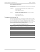
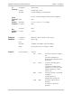
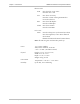
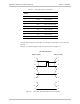
Table Of Contents
- Contents
- Introduction
- Installation
- Operation
- Introduction
- Front Panel Controls, Connectors, and Indicators
- Operating Instructions
- Getting Started
- Menu Operations
- Configuring System Parameters
- Configuring IPmux-16
- Troubleshooting and Diagnostics
- Boot Sequence for Downloading Software
- SNMP Management
- Telnet
- TFTP Download Procedures
- DC Power Supply Connection – CBL-DC-3WL/F
IPmux-16 Installation and Operation Manual Chapter 2 Installation
Equipment Needed 2-3
Table 2-1. Null Cable Pinout Connections
DB-9 Female
Pin No.
Signal Name
1 DCD Data Carrier Detect
2 RXD Receive data
3 TXD Transmit data
4 DTR Data Terminal Ready
5 GND Ground
6 DSR Data Set Ready
7 RTS Request To Send
8 CTS Clear To Send
9 RI Ring Indicator
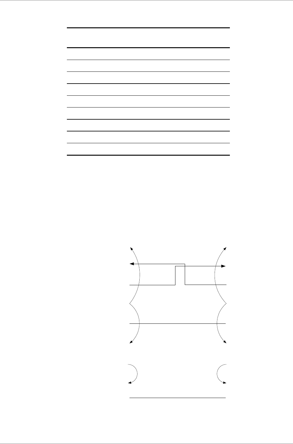
On both DB9 connectors, DCD (pin 1), DTR (pin 4) and DSR (6) are connected
together.
RTS (pin 7) is shorted together with CTS (pin 8). Refer to Figure 2-1.
CBL-DB-9/DB9/NULL
DB-9 (Female)
DB-9 (Female)
1
2
3
4
5
7
8
6
99
8
7
6
5
4
3
2
1
Figure 2-1. Null Cable (CBL-DB-9/DB-9/NULL) Pin Shorts