
- RAD Data Communications Network Router User Manual
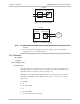
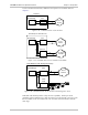
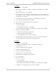
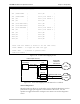
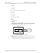
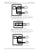
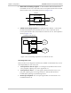
Table Of Contents
- Front Matter
- Quick Start Guide
- Contents
- Chapter 1 Introduction
- Chapter 2 Installation and Setup
- Chapter 3 Operation
- Chapter 4 Configuration
- Chapter 5 Setup Menu
- Chapter 6 Troubleshooting and Diagnostics
- Appendix A Interface Specifications and Cable Diagrams
- Appendix B Boot Manager
- Appendix C SNMP Management
- Appendix D Glossary
- DC Power Supply Connection
- Customer Response Form
FCD-IPM Installation and Operation Manual Chapter 5 Setup Menu
Interface Parameters Menu 5-39
Link1
FCD-IPM (T1 with Sub Link)
Router/Bridge
Sub Link T1
Interface
Analog
Front End
Loopback
T1
Service
T1 Service
or PABX
Figure 5-45. Remote Analog Loopback for T1 and Sub T1 Links
• Main Link Remote Digital Loopback – In this mode FCD-IPM performs a
digital loopback and transmits back the signal that was received from the T1
line. The loopback is shown in Figure 5-46.
Link1 T1 Interface
Loopback
FCD-IPM
Digital
Front End
T1
Service
Figure 5-46. Remote Digital Loopback
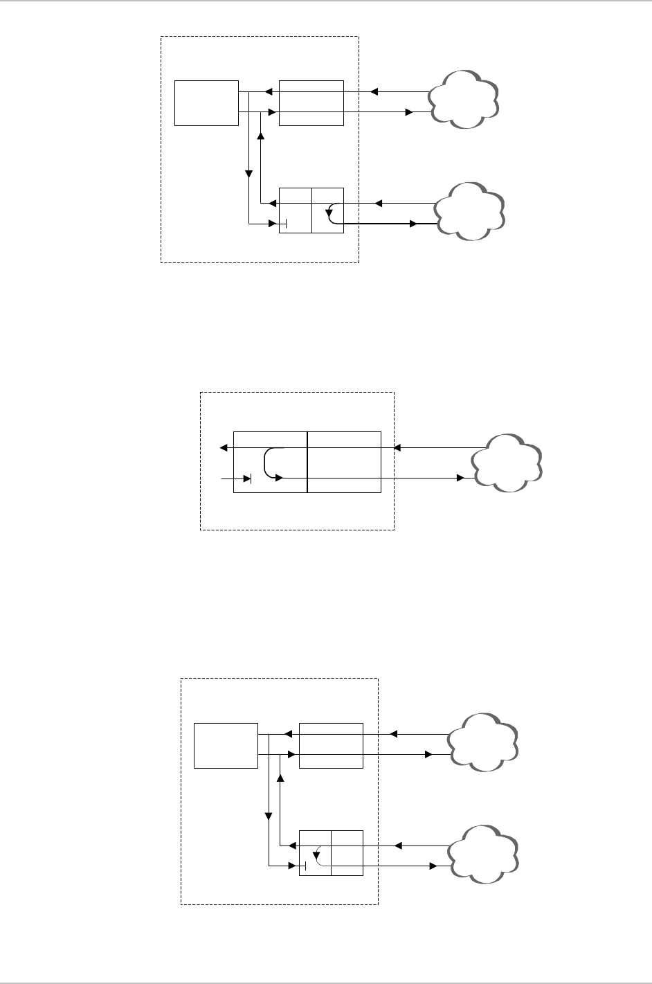
• Sublink Remote Digital Loopback (for FCD-IPM with a sublink) – In this
mode
FCD-IPM performs a digital loopback and transmits back the signal that was
received from the sub T1 line. The loopback is shown in Figure 5-47.
Link1
FCD-IPM (T1 with Sub Link)
Router/Bridge
Sub Link T1
Interface
Digital
Front End
Loopback
T1
Service
T1 Service
or PABX
Figure 5-47. Remote Digital Loopback for T1 and Sub T1 Links