RSD-20 High Speed Digital Sharing Device Installation and Operation Manual Notice This manual contains information that is proprietary to RAD Data Communications. No part of this publication may be reproduced in any form whatsoever without prior written approval by RAD Data Communications. No representation or warranties for fitness for any purpose other than what is specifically mentioned in this manual is made either by RAD Data Communications or its agents.
:DUUDQW\ 7KLV 5$' SURGXFW LV ZDUUDQWHG DJDLQVW GHIHFWV LQ PDWHULDO DQG ZRUNPDQVKLS IRU D SHULRG RI RQH \HDU IURP GDWH RI VKLSPHQW 'XULQJ WKH ZDUUDQW\ SHULRG 5$' ZLOO DW LWV RSWLRQ HLWKHU UHSDLU RU UHSODFH SURGXFWV ZKLFK SURYH WR EH GHIHFWLYH )RU ZDUUDQW\ VHUYLFH RU UHSDLU WKLV SURGXFW PXVW EH UHWXUQHG WR D VHUYLFH IDFLOLW\ GHVLJQDWHG E\ 5$' %X\HU VKDOO SUHSD\ VKLSSLQJ FKDUJHV WR 5$' DQG 5$' VKDOO SD\ VKLSSLQJ FKDUJHV WR UHWXUQ WKH SURGXFW WR %X\HU +RZHYHU %X\HU VKDOO SD\ DOO VKLSSLQJ FKDUJHV GXWLH
6DIHW\ :DUQLQJV 7KH H[FODPDWLRQ SRLQW ZLWKLQ D WULDQJOH LV LQWHQGHG WR ZDUQ WKH RSHUDWRU RU VHUYLFH SHUVRQQHO RI RSHUDWLRQ DQG PDLQWHQDQFH IDFWRUV UHODWLQJ WR WKH SURGXFW DQG LWV RSHUDWLQJ HQYLURQPHQW ZKLFK FRXOG SRVH D VDIHW\ KD]DUG $OZD\V REVHUYH VWDQGDUG VDIHW\ SUHFDXWLRQV GXULQJ LQVWDOODWLRQ RSHUDWLRQ DQG PDLQWHQDQFH RI WKLV SURGXFW 2QO\ D TXDOLILHG DQG DXWKRUL]HG VHUYLFH SHUVRQQHO VKRXOG FDUU\ RXW DGMXVWPHQW PDLQWHQDQFH RU UHSDLUV WR WKLV LQVWUXPHQW 1R DGMXVWPHQW PDLQWHQDQFH RU UHSDLUV VKRXOG EH
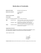
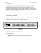
'HFODUDWLRQ RI &RQIRUPLW\ Manufacturer’s Name: RAD Data Communications Ltd. Manufacturer’s Address: 12 Hanechoshet St. Tel Aviv 69710 Israel declares that the product: Product Name: RSD-10 Conforms to the following standard(s) or other normative document(s): EMC: Safety: EN 55022 (1994) Limits and methods of measurement of radio disturbance characteristics of information technology equipment.
TABLE OF CONTENTS 1 INTRODUCTION 1.1 1.2 1.3 1.4 General . . . . . . . Functional Description Specifications . . . . Ordering . . . . . . . . . . . . . . . . . . . . . . . . . . . . . . . . . . . . . . . . . . . . . . . . . . . . . . . . . . . . . . . . . . . . . . . . . . . . . . . . . . . . . . . . . . . 1.1 1.1 1.2 1.3 2 INSTALLATION 2.1 2.2 2.3 2.4 2.5 General . . . . . . . . . . . . . . . . . . . . Site Preparation . . . . . . . . . . . . . . . . Physical Installation . . .
1 INTRODUCTION 1.1 GENERAL The RSD-20, High Speed Digital Sharing Device, enables up to four high speed modems, terminals or controllers to share a master modem, a multiplexer or a computer port in a multipoint environment. The RSD-20 is compatible with synchronous equipment at data rates of 48, 56, or 64 kbps, with V.35 or X.21 interface. 1.2 FUNCTIONAL DESCRIPTION The main channel transmits information to all sub-channels in parallel.
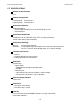
RSD-20 OPERATOR'S MANUAL INTRODUCTION 1.3 SPECIFICATIONS Number of Sub-channels Four Channel Configuration Lowest priority: Highest priority: Sub-channel 1 Sub-channel 4 Sub-channel Selection Strap-selectable to: Control signal RTS/DCD (V.35) or CONT/IND (X.21) ON Data transitions Sub-channel Deselection RTS/DCD (V.35) or CONT/IND (X.
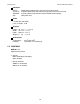
INTRODUCTION RSD-20 OPERATOR'S MANUAL Indicators DATA: ACTIVITY: DISABLE: ON: Display data broadcast from main channel to sub-channels 4 LEDs indicate which sub-channel has gained access to main channel 4 LEDs indicate if sub-channel has been disabled automatically RSD power is on Power 115/230 VAC switchable; 10%; 47-63 Hz; 10 W Physical Height: Width: Depth: Weight: 44 mm 431 mm 208 mm 2 kg / / / / 1.7 in (1U) 17.0 in 8.2 in 4.
2 INSTALLATION Access inside the equipment is only permitted to authorized service personnel. 2.1 GENERAL This chapter provides information on performing the mechanical and electrical installation of the RSD-20. After installation has been completed, refer to Chapter 3 for operating information and system checkout to assure normal operation. 2.2 SITE PREPARATION The RSD-20 must be installed within 1.5 m (5 feet) of a grounded AC outlet, and within 15 m (50 feet) of the associated data terminals or modems.
INSTALLATION RSD-20 OPERATOR'S MANUAL 2.4.2 Rear Panel Six connectors are located on the rear panel of the RSD-20, consisting of five channel connectors (four for the sub-channels and one for the main channel) and one 3-pin power connector, which also includes the fuse holder. The five channel connectors are 34-pin connectors for the V.35 interface or 15-pin, D-type for the X.21 interface. The ON/OFF power switch and the 110/220 VAC selection switch are located also on the rear panel (see Figure 2.1). 2.
RSD-20 OPERATOR'S MANUAL INSTALLATION 2.
INSTALLATION RSD-20 OPERATOR'S MANUAL 2.
RSD-20 OPERATOR'S MANUAL INSTALLATION 2.5 SYSTEM SYNCHRONIZATION AND CLOCK DISTRIBUTION 2.5.1 RSD-20/V.35 Four alternatives are available for synchronization of the system: a) Main channel modem timing signals. b) RSD-20 internal clock. c) Sub-channel 1 modem timing signals. d) Any sub-channel modem timing signals. For this the optional buffer is required. 2.5.1.1 Synchronization on Main Channel Modem Clock a) Main channel modem – strapped to internal clock.
INSTALLATION RSD-20 OPERATOR'S MANUAL 2.5.1.2 Synchronization on RSD-20 Internal Clock a) RSD-20 baud rate should be strapped to the required speed. b) DCEs attached to sub-channels should be strapped to external clock. c) DCE attached to main channel should be strapped to external clock. EXT. CLK RSD-20 EXT. CLK DCE EXT. CK SUB DTE TX. CLK SUB-CHANNEL MAIN DTE DCE EXT. CK TX. CLK SUB DCE DTE EXT. CK TX. CLK MAIN DTE Figure 2.5 Synchronization on Internal Clock 2.
RSD-20 OPERATOR'S MANUAL INSTALLATION 2.5.1.3 Synchronization on Sub-channel 1 a) RSD-20 baud rate should be strapped to CLK-1. b) DCE attached to main channel should be strapped to external clock. c) DCEs attached to sub-channel 1 should be strapped to internal clock. NOTE Synchronization on sub-channel 1 is not recommended when the modem connected to sub-channel 1 operates in switched carrier mode, as it causes fluctuations in clock frequency and phase. EXT. CLK DCE EXT.
INSTALLATION RSD-20 OPERATOR'S MANUAL 2.5.1.4 External Clock for more than one Sub-channel This option enables connection of more than one sub-channel to the line from the P.T.T. service. Generally, the P.T.T. modems supply clock to every line – i.e. the P.T.T. has to provide the clock. Since the modems are all from the same service, the clocks are synchronized. The external buffer will compensate for phase differences between the clocks received from the sub-channels.
RSD-20 OPERATOR'S MANUAL INSTALLATION 2.5.2.4 Main channel is DCE and sub-channels are mixed (DTE and DCE) In this mode one of the modems attached to the sub-channels (configured as DTE) should be attached to sub-channel 1, and the RSD baud rate should be strapped to CLK-1.
3 OPERATION 3.1 GENERAL This chapter details the RSD-20 controls and indicators, their functions, and operating procedures. The installation procedures given in Chapter 2 must be completed and checked before operation of the RSD-20 is attempted. NOTE For an explanation of all the possible system installations of the RSD-20, refer to Chapter 4. 3.2 CONTROLS AND INDICATORS SUB-CHANNEL DISABLE RAD RSD-20 POWER DATA AUTOMATIC ACTIVITY 1 2 3 4 1 2 3 4 1 2 3 4 Figure 3.
RSD-20 OPERATOR'S MANUAL OPERATION Table 3.1 Control Functions Control Location Function Power switch (with lamp) ON/OFF Rear Panel Turns AC power ON or OFF 110/220 VAC Selector Rear Panel Selects main power source: 115 or 230 VAC Four manual DISABLE push-button switches Front Panel Manually deactivates sub-channels connected to defective terminals or modems. A depressed push button disables the sub-channel Table 3.
OPERATION RSD-20 OPERATOR'S MANUAL 3.4 OPERATIONAL FIELD STRAPPING CHANGES Access inside the equipment is only permitted to authorized service personnel. If it becomes necessary to reconfigure the RSD-20 for a different type of operation, the internal straps must be changed to correspond to the new operating mode. For guidance in repositioning the straps, refer to the information given in Chapter 2 of this manual. It is recommended that the straps be changed by an experienced technician.
RSD-20 OPERATOR'S MANUAL THEORY OF OPERATION AND APPLICATIONS 4 THEORY OF OPERATION AND APPLICATIONS 4.1 INTRODUCTION This chapter contains a simplified functional description of the RSD-20, and covers the flow of data, controls and clocks in all RSD-20 operating modes. 4.2 CONTENTION RTS/DCD contention in V.35 interface is interchangeable with CONTROL/INDICATION contention for X.21 interface.
4.4 CONTROL SIGNALS Sub-channel control signals are combined to provide a composite signal to the main channel. Control signals from the main channel are passed to all sub-channels in parallel. The following are details of control signals: 4.4.1 Main Channel Control Signals 4.4.1.1 RSD-20/V.35 RTS (DCD) In RTS/DCD (CONTROL/INDICATION) contention mode – Follows RTS (DCD) of the selected sub-channel. In Data Contention mode – “ON” if RTS (DCD) of one of the sub-channels is “ON”.
RSD-20 OPERATOR'S MANUAL THEORY OF OPERATION AND APPLICATIONS 4.4.2.2 RSD-20/X.21 CONTROL/INDICATION If the “C/I to Sub-channel” jumper is in the “MAIN CHANNEL” state, the C/I to sub-channel follows the main C/I (unless the sub-channel is disabled, then the C/I is OFF). If the “C/I to sub-channel is in the ”ON" state, all of the sub-channels’ C/O are “ON” irrespective of the main channel C/I. 4.
THEORY OF OPERATION AND APPLICATIONS RSD-20 OPERATOR'S MANUAL 4.
RSD-20 OPERATOR'S MANUAL THEORY OF OPERATION AND APPLICATIONS Figure 4.1 Main Channel DTE with Sub-channel DCE Figure 4.2 Main Channel DCE with Sub-channel DTE 4.
THEORY OF OPERATION AND APPLICATIONS RSD-20 OPERATOR'S MANUAL Figure 4.3 Main channel DTE with Sub-channel DTE Figure 4.4 Main channel DCE with Sub-channel DCE 4.
RSD-20 OPERATOR'S MANUAL THEORY OF OPERATION AND APPLICATIONS 4.5 APPLICATIONS The RSD-20 operates in one of six modes: modem sharing, port sharing, remote port sharing, local port sharing, mix modem sharing and mix port sharing. System configurations incorporating the RSD-20 in each operating mode are described in Figure 4.1.
APPENDIX A Table A.1 X21 Interface Signal Description X.
APPENDIX B Table B.1 V.35 Interface Signal Description V.