
- RAD IPmux-11 TDM Pseudowire Access Gateway Version 2.00 Installation and Operation Manual


Chapter 2 Installation and Setup Installation and Operation Manual
2-2 Connecting the Ethernet Equipment IPmux-11 Ver. 2.00
2.3 Package Contents
The IPmux-11 package includes the following items:
• One IPmux-11 unit
• Power cord
• IEC 60320 AC/DC adapter plug
• CBL-DB9F-DB9M-STR control port cable (if ordered)
• CBL-RJ45/2BNC/E1/X adapter cable for unbalanced E1 interface (if ordered)
• RM-33-2 rack mount kit (if ordered).
2.4 Connecting the Ethernet Equipment
IPmux-11 is connected to the Ethernet network equipment via the fiber optic LC
or 8-pin RJ-45 electrical port designated ETH 1. Connection to the Ethernet user
equipment is made via two 8-pin RJ-45 electrical ports designated ETH 2 and
ETH 3. Refer to Appendix A for the RJ-45 connector pinout.
Connecting the Ethernet Network Equipment
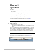
Figure 2-1 and Figure 2-2 illustrate typical rear panels of the IPmux-11 unit with
fiber optic LC and electrical RJ-45 network connectors, respectively.
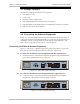
To connect to the Ethernet network equipment with fiber optic interface:
• Connect IPmux-11 to the Ethernet network equipment using a standard fiber
optic cable terminated with an LC connector.
CONTROL
EXT CLK E1
ETH
123
SET
DEF
Figure 2-1. ETH 1 Fiber Optic Connector
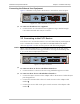
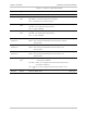
To connect to the Ethernet network equipment with a copper interface:
• Connect IPmux-11 to the Ethernet network equipment using a standard
straight UTP cable terminated with an RJ-45 connector.
CONTROL
EXT CLK E1
ETH
123
SET
DEF
Figure 2-2. ETH 1 Electrical Connector