HCD-E1 HDSL CSU/DSU Installation and Operation Manual Notice This manual contains information that is proprietary to RAD Data Communications. No part of this publication may be reproduced in any form whatsoever without prior written approval by RAD Data Communications. No representation or warranties for fitness for any purpose other than what is specifically mentioned in this manual is made either by RAD Data Communications or its agents.
Warranty This RAD product is warranted against defects in material and workmanship for a period of one year from date of shipment. During the warranty period, RAD will, at its option, either repair or replace products which prove to be defective. For warranty service or repair, this product must be returned to a service facility designated by RAD. Buyer shall prepay shipping charges to RAD and RAD shall pay shipping charges to return the product to Buyer.
Telecommunication Safety The safety status of each of the ports on HCD-E1 are declared according to EN41003 and is detailed in the table below. Interconnection of these ports with other apparatus should be made such that the equipment continues to comply with clause 2.3 of EN60950 for SELV circuits after such a connection is made.
Declaration of Conformity Manufacturer’s Name: RAD Data Communications Ltd. Manufacturer’s Address: 24 Raoul Wallenberg St. Tel Aviv 69719 Israel declares that the product: Product Name: HCD-E1 Conforms to the following standard(s) or other normative document(s): EMC: Safety: EN 55022 (1994) Limits and methods of measurement of radio disturbance characteristics of information technology equipment.
Quick Start Guide Installation of HCD-E1 should be carried out only by an experienced technician. If you are familiar with RAD's HDSL modems, use this guide to prepare HCD-E1 for operation. 1. Installing HCD-E1 Switch and Jumper Settings HCD-E1 contains two sets of jumpers: • • Main board internal jumpers and DIP switch E1 sublink interface board jumpers. If you are using HCD-E1 as a central unit (LTU), you can use the default settings for the main board R/C jumper and DIP switch.
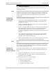
HCD-E1 Installation & Operation Manual Quick Start Guide 7. Set the JP12 jumper to UNBAL E1. 8. Set the JP16 and JP17 jumpers to UNBAL. 9. Connect the JP9 jumper. 10. Install the JP8 and JP10 jumpers. 11. Reinstall the sublink interface board by reversing the procedure by which you removed it. Pay special attention to the following: Mate correctly the flat cable connector with the corresponding main board connector.
HCD-E1 Installation & Operation Manual Quick Start Guide 2. Configuring HCD-E1 You can configure and operate HCD-E1 from either the front panel or a supervisory terminal. Note Configuring HCD-E1 from Front Panel Note Some of the HCD-E1 configuration parameters depend on the type of remote unit being used. Therefore, after the HDSL synchronization is reached, wait for about 1 minute before you start configuring the modem.
HCD-E1 Installation & Operation Manual Quick Start Guide 2. Connect the terminal to the CONTROL DCE port of HCD-E1. 3. Press three times. 4. If the terminal displays the password prompt (PASSWORD>), enter the password. The default password is HCD. If the node number of HCD-E1 is a number other than zero, enter the node number along with the password.
HCD-E1 Installation & Operation Manual Quick Start Guide 12. You can assign each HCD-E1 unit a logical name of up to eight characters. The logical name helps identify the source of alarm messages that HCD-E1 sends to the supervision terminal. Use the DEF NAME command to assign a logical name. 13. To reset HCD-E1, use the RESET command. 14. To reset a configuration of HCD-E1 to default values, use the INIT DB command.
Quick Start Guide 6 Configuring HCD-E1 HCD-E1 Installation & Operation Manual
Contents CHAPTER 1 INTRODUCTION 1.1 Overview ....................................................................................................................... 1-1 General ................................................................................................................................ 1-1 Versions................................................................................................................................ 1-1 Applications.................................................
Table of Contents 3.4 Configuration Parameters ............................................................................................... 3-7 3.5 Operating Instructions.................................................................................................. 3-19 Turning HCD-E1 On ........................................................................................................... 3-19 Checking the Current Operating Configuration ..........................................................
Table of Contents DSP ALM REM.................................................................................................................... 4-31 DSP BERT CH..................................................................................................................... 4-31 DSP HDR TST .................................................................................................................... 4-33 DSP HDSL PM.................................................................................
Table of Contents 5.5 Configuration Error Messages ....................................................................................... 5-31 5.6 Power-Up Self-Test ...................................................................................................... 5-34 5.7 Troubleshooting ...........................................................................................................
Table of Contents List of Figures Figure 1-1 Typical HCD-E1 Application ........................................................................................ 1-2 Figure 1-2 HCD-E1 3D View ........................................................................................................ 1-6 Figure 1-3 Basic Management Topology Using Network Management Station ............................ 1-10 Figure 1-4 Extended Management Topology Using Network Management Station......................
Table of Contents List of Tables Table 1-1 Automatically-Selected FIFO Size Values .................................................................... 1-16 Table 2-1 HCD-E1 Interface Adapter Cables............................................................................... 2-11 Table 3-1 Table 3-2 Table 3-3 Table 3-4 Table 3-5 Table 3-6 Table 3-7 Table 3-8 HCD-E1 Controls, Connectors and Indicators ............................................................... 3-2 System Parameters...................
Chapter 1 Introduction 1.1 Overview General HCD-E1 is a standalone HDSL NTU (Network Terminal Unit) / LTU (Line Terminal Unit) that provides the user with one E1 sublink drop & insert port and two n × 64 kbps or n × 56 kbps data channels. Fractional E1 from the E1 sublink, as well as data from the n × 64 kbps / n × 56 kbps channels are multiplexed over E1 frames and transferred by the HDSL modem to the remote location.
HCD-E1 Installation & Operation Manual Chapter 1 - Introduction When you order a unit with a V.35, V.36/RS-449, or X.21 interface, you receive a unit with the RS-530 interface provided with a corresponding adapter cable. HCD-E1 is available in the AC and DC versions. The AC version is powered by 100 to 240 VAC, 50 or 60 Hz. As an option, HCD-E1 can also be ordered with a -48 VDC power supply.
HCD-E1 Installation & Operation Manual Chapter 1 - Introduction • Remote loopbacks on the data channel and E1 sublink of the local HCD-E1 • Remote loopbacks on the data channel and E1 sublink of the remote unit. • Inband-activated remote loopback on the data channel of remote HCD-E1 • H-RPT local loop (towards the HCD-E1 configured as central) when working with the HDSL repeater.
HCD-E1 Installation & Operation Manual Chapter 1 - Introduction To expedite the routing, HCD-E1 supports two “bundle” routing modes, called “sequential bundle” and “alternate bundle” modes.
HCD-E1 Installation & Operation Manual Chapter 1 - Introduction Figure 1-2 HCD-E1 3D View Front Panel The front panel provides control over the unit operation. The LEDs provide real-time indications related to the operation and status of the unit. The LCD together with three push-button switches are used to display status (alarm) messages, diagnostics and performance monitoring data, test status and configuration parameters of HCD-E1. You can also use the LCD and push buttons to configure the unit.
HCD-E1 Installation & Operation Manual Chapter 1 - Introduction Each HCD-E1 data port supports the following control lines: E1 Link Interface Characteristics • RTS - input from the locally connected data equipment • CTS - the user can permanently set the CTS line in the active state, or can make the CTS line follow the RTS line. • DSR - the DSR line is always active when the HCD-E1 is powered, except when a remote main link test loopback is activated.
HCD-E1 Installation & Operation Manual Chapter 1 - Introduction The transmission of data on each twisted-wire pair (HDSL line) is full duplex, and except for the distribution of payload data bits between the two lines, each HDSL line operates independently. HCD-E1 provides an embedded operations channel (eoc) within the HDSL data streams, which enables end-to-end system management and supervision. The HDSL subsystem operates in a master-slave mode.
HCD-E1 Installation & Operation Manual Chapter 1 - Introduction The remote management capabilities available through the serial RS-232 port are as follows: • Management by means of a Supervision Terminal • Management by means of Telnet • SNMP Management. If you have an H-RPT on your link, you can use either SP or Telnet management to display the status messages of H-RPT and, if your application allows this, connect/disconnect the H-RPT loop (from the unit configured as central).
HCD-E1 Installation & Operation Manual Chapter 1 - Introduction A basic management topology, which is suitable for both SNMP and Telnet management, is shown in Figure 1-3. In this example, a network management station is attached to an Ethernet LAN. A remote access LAN extender, MBE/RAS/A, is located near the managed equipment (such as HCD-E1, MEGAPLEX-2100(*), etc.), and its serial ports are connected via cables to the CONTROL connectors of the equipment.
HCD-E1 Installation & Operation Manual Chapter 1 - Introduction Each SNMP agent recognizes the messages addressed to its own IP address. In addition, the SNMP agent includes a proprietary built-in IP router, which is able to route management messages in accordance with the network topology determined by the routing algorithm, without requiring the user to provide a priori topology information on the network.
HCD-E1 Installation & Operation Manual Chapter 1 - Introduction For example, the following paths can be made available for the management traffic, when the management station is attached to HCD-E1: • The network is connected to the network management station using a single serial communication link, attached to the CONTROL DCE port of HCD-E1 (system 1). • In-band communication through the HCD-E1 No.
HCD-E1 Installation & Operation Manual Chapter 1 - Introduction System Timing HCD-E1 offers selectable timing options, which enable the distribution of timing over the HDSL system, from the central office to the remote end. The use of stuffing on the HDSL subsystem ensures that the E1 signal and the data rate provided to the customer equipment by the remote unit are locked to the timing of the E1 signal and data rate received by the central unit.
HCD-E1 Installation & Operation Manual Chapter 1 - Introduction REMOTE HCD-E1 HDSL LINE A INTERNAL TIMING HDSL LINE INTERFACE HDSL LINE A INTERFACE LOOPBACK TIMING LOOPBACK TIMING NETWORK SIDE E1 INTERFACE DATA EQUIPMENT DATA CHANNEL 1 INTERFACE DATA EQUIPMENT DATA CHANNEL 2 INTERFACE HDSL LINE B HDSL LINE B INTERFACE E1 INTERFACE CUSTOMER SIDE (DTE) DATA CHANNEL 1 INTERFACE DATA EQUIPMENT DATA CHANNEL 2 INTERFACE DATA EQUIPMENT HDSL LINE B INTERFACE CENTRAL HCD-E1 Figure 1-6 Flow of Ti
HCD-E1 Installation & Operation Manual Chapter 1 - Introduction Figure 1-7 Data Channel Timing, Flow of Timing Signals in a Typical Application In the application shown in Figure 1-7, the data equipment located on the customer’s premises uses the HCD-E1 link to connect to a data network.
HCD-E1 Installation & Operation Manual Chapter 1 - Introduction Table 1-1 Automatically-Selected FIFO Size Values Data Channel Rate FIFO Size 64 kbps ±16 bits 128 and 192 kbps ±30 bits 256 to 448 kbps ±52 bits 512 to 1536 kbps ±72 bits 1600 to 1792 kbps ±52 bits 1856 and 1920 kbps ±30 bits 1984 and 2048 kbps ±16 bits Sublink Timing Application Figure 1-8 shows a typical application which uses the sublink as the timing reference source, and illustrates the flow of timing signals within the
HCD-E1 Installation & Operation Manual Chapter 1 - Introduction Figure 1-8 Sublink Timing, Flow of Timing Signals in a Typical Application Main Principles of This section describes the E1 and the HDSL environments, to provide the background information required for the understanding of the configuration Operation parameters of the HCD-E1 system. The E1 (CEPT) Environment The E1 line interfaces of the HCD-E1 comply with the applicable requirements of ITU-T Rec. G.703, G.704, G.706, G.732, and G.823.
HCD-E1 Installation & Operation Manual Chapter 1 - Introduction Time Slot 0 Time Slot 16 a. Even Frames (0,2,4-14) 8 Bits/ Time Slot 1 0 0 1 1 0 1 1 a. Frame 0 0 0 0 0 X Y X X FAS MAS b. ODD Frames (1,3,5-15) I 1 A N N N N N 32 Time Slots/Frame 16 Frames/Multiframe TS 0 TS 1 FR 0 Time Slots 1-15, 17-31 TS 2 TS 3 FR 1 TS 4 Channel Data b.
HCD-E1 Installation & Operation Manual Chapter 1 - Introduction − Bit 3 - this bit is used as a Remote Alarm Indication (RAI), to notify the equipment at the other end that the local equipment lost frame alignment, or does not receive an input signal. − The other bits, identified as Sa4 through Sa8, are designated national bits, and are actually available to the users, provided agreement is reached as to their use. RAD equipment with SNMP agents can use the Sa4 bit for in-band management traffic.
HCD-E1 Installation & Operation Manual Chapter 1 - Introduction At the receiving end, the checksum is calculated again on each submultiframe and then compared against the original checksum (sent by the transmitting end in the next submultiframe). The results are reported by two bits multiplexed in bit 1 of time slot 0 in frames 13, 15 of the CRC-4 multiframe, respectively. Errors are counted and used to prepare statistic data on transmission performance.
HCD-E1 Installation & Operation Manual Chapter 1 - Introduction HDSL Environment Transmission Media HDSL systems are intended to operate on the local subscriber plant, which typically uses a mixture of unshielded twisted-wire pairs. Moreover, it is also necessary to tolerate bridged taps. HDSL systems properly operate on this media. The only requirement is that the lines must not be loaded.
HCD-E1 Installation & Operation Manual Chapter 1 - Introduction By reducing the line symbol rate, the maximum range that can be reached is increased. Together with the advanced digital signal processing techniques implemented in HDSL systems, this results in a robust data transmission system that can reliably operate over regular unconditioned local loops, while exceeding several times the ranges that can be achieved by direct transmission of an E1 signal.
HCD-E1 Installation & Operation Manual Chapter 1 - Introduction 2048 kbps Data at the Application Frame Interface Time Slots Inserted in Core Frame with 2048 kbps Data TS0 0 TS0 TS0 1 TS1 TS1 2 TS2 TS2 3 TS3 TS3 4 TS4 TS4 5 TS5 TS5 6 TS6 TS6 7 TS7 TS7 8 TS8 TS8 9 TS9 TS9 10 TS10 TS10 11 TS11 TS11 12 TS12 TS12 13 TS13 TS13 14 TS14 TS14 15 TS15 ⇔ TS15 16 ⇔ TS16 Mapping into TS16 17 Mapping to the TS17 Core Frames TS16 18 two HDSL Lines TS18 TS1
HCD-E1 Installation & Operation Manual Chapter 1 - Introduction HDSL-Related System Functions The HDSL subsystem performs the following main functions: • Mapping of input data bits into HDSL frames, for transmission on the HDSL lines • Start-up process • Frame alignment • Loop identification and correction • System management by means of the eoc channel • Collection of performance data.
HCD-E1 Installation & Operation Manual Chapter 1 - Introduction 1.4 Technical Specifications HDSL Interface Compliance ETSI TR-152 Signal Format Dual duplex, 2B1Q line coding Line Baud Rate 584 kbaud (equivalent to 1168 kbps), for each pair Line Type Two unconditioned, unloaded twisted pairs Impedance 135Ω Transmit Pulse Shape As per ETSI TR-152 Transmit Signal Power +13.5 dBm ± 0.5 dBm Loop Loss 31 dB max at 150 kHz (584 kbaud) Range - Without H-RPT Up to 3.8 km (2.
HCD-E1 Installation & Operation Manual Chapter 1 - Introduction Signal Levels Transmit Levels - Balanced interface: ±3V ±10% - Unbalanced interface: ±2.37V ±10% Receive LEVELS 0 to -10 dB Jitter Performance Per ITU G.823 Connectors - Balanced interface: 8-pin RJ-45 female connector - Unbalanced interface: two BNC coaxial connectors Data Channel Interface Data Rate Multiples of 56 or 64 kbps, up to 2.
HCD-E1 Installation & Operation Manual Chapter 1 - Introduction Diagnostics Loopbacks - HDSL main link local loopback, towards the E1 sublink and data channels of the local unit - Channel loopback on the local unit towards the DTE connected to the data channel of the remote unit (per channel) - Channel loopback on the remote unit towards the DTE connected to the data channel of the local unit (per channel) - Channel loopback on the local unit towards the DTE connected to its data channel (per channel) -
HCD-E1 Installation & Operation Manual Chapter 1 - Introduction E1 Sublink Receive Timing Always recovered from the E1 sublink receive data signal Transmit Timing (user-selectable) Follows the transmit timing of the HDSL link. Synchronous Data Channels - DCE timing mode: HCD-E1 data channel provides transmit and receive clocks for the DTE connected to the data port.
HCD-E1 Installation & Operation Manual Chapter 1 - Introduction Power Environment 1-28 AC Source 100 ÷240 VAC, 50 or 60 Hz DC Source -48 VDC (-36 VDC to -72 VDC) Operating Temperature 0 ÷50°C (32 ÷122°F) Relative Humidity Up to 90%, non-condensing Technical Specifications 01/01/01 08:07
Chapter 2 Installation and Setup This chapter describes installation procedures for the standalone HCD-E1 device. For instructions on installation of one or two units in a 19-inch rack, refer to the Rack Mounting Kit for 19-inch Racks guide that comes with the RM kit. After installing the unit: • Refer to Chapter 3 for detailed system configuration information and procedures using the front panel controls.
Chapter 2 - Installation and Setup HCD-E1 Installation & Operation Manual 2.2 Package Contents The HCD-E1 package includes the following items: • HCD-E1 unit • HCD-E1 Installation and Operation Manual • AC power cord or DC power supply connector kit. • Interface adapter cable/s (interface ordering options, see Connecting the Interfaces later in this chapter). 2.3 Installation and Setup HCD-E1 is a standalone device designed for tabletop or bench installation. It is delivered completely assembled.
HCD-E1 Installation & Operation Manual Chapter 2 - Installation and Setup RJ-45 Connector S1 ON SPARE DB INIT DEF SP PASSWD Data Channel 2 Interface Board Sublink Interface Board Jumper C/R R R Remote Unit R/C C Central Unit JP4 C J10 FGND/GND Connected JP8 FGND/GND ON ON OFF Not OFF Connected Figure 2-1 HCD-E1 - Identification of Boards, Jumpers and Switches The Main Board contains the common signal processing circuits, the interfaces to the main link (HDSL) and the Data Channel 1 i
Chapter 2 - Installation and Setup HCD-E1 Installation & Operation Manual Access to the inside of the equipment is permitted only to authorized and qualified service personnel. Warning To avoid accidental electric shock, always disconnect the interface cables and the power cord before removing the unit from its casing. Line voltages are present inside HCD-E1 when it is connected to power and/or to the lines.
HCD-E1 Installation & Operation Manual Chapter 2 - Installation and Setup Cover Screws (4 Places) Figure 2-2 Identification of Cover Screws Setting the Main Board Internal Jumpers and Switches The internal jumpers and switches located on the HCD-E1 main board are identified in Figure 2-1. The functions of jumpers and switches are described below.
HCD-E1 Installation & Operation Manual Chapter 2 - Installation and Setup • Switch section 3 – DEF SP. This section selects the source of the control port parameters: ON HCD-E1 uses the default parameters stored in its program EPROM. For the default values, see Table 3-4 in Chapter 3. OFF HCD-E1 uses the parameters stored in the database. HCD-E1 is shipped with section 3 set at OFF. • Switch section 4 – PASSWD.
HCD-E1 Installation & Operation Manual Warning Chapter 2 - Installation and Setup Setting the FGND/GND jumper to OFF may make the equipment unsafe for direct connection to unprotected telecommunication networks at locations where constant excessive voltages may be present on the lines. Removing the E1 Sublink Interface Board The E1 sublink interface board is located over the main board, and is installed with the component side facing the main board.
HCD-E1 Installation & Operation Manual Chapter 2 - Installation and Setup Setting the Sublink Interface Board Jumpers Figure 2-4 shows the component side of the E1 sublink interface board, as seen after it is removed from the unit. Note The interface board has protection fuses for the surge protection circuits located on the line side of the line isolation transformers. These fuses are also identified in Figure 2-4.
HCD-E1 Installation & Operation Manual • Chapter 2 - Installation and Setup For operation with the unbalanced interface: − Set the jumper JP12 to UNBAL E1. − Set the jumpers JP16 and JP17 to UNBAL. − Connect the jumper JP9. HCD-E1 is shipped with all the jumpers set for balanced interface. E1 Sublink Transmit Side Ground Reference Jumper, JP8 The jumper JP8 controls the ground reference of the E1 sublink transmit output when working with the unbalanced interface.
HCD-E1 Installation & Operation Manual Chapter 2 - Installation and Setup Reinstalling the HCD-E1 Cover After completing the internal settings, reinstall the top cover as follows: 1. Position the lower half of the HCD-E1 case on a flat, clean surface. Check that the decorative black plastic strips on the sides of the unit are still in place (if not, place the strips in the grooves on the sides of the lower half). 2.
HCD-E1 Installation & Operation Manual Chapter 2 - Installation and Setup Connecting the Data Channels HCD-E1 typically has two data ports, each terminated in a 25-pin D-type female connector. The units with an Ethernet interface arrive with the Ethernet interface module built in the upper port. For the description of the Ethernet interface, see Appendix C and Appendix D.
Chapter 2 - Installation and Setup HCD-E1 Installation & Operation Manual Connecting the Control Port If you are using the control terminal, connect a cable prepared in accordance with Appendix B between the control port connector, designated CONTROL DCE (see Figure 3-1 in Chapter 3), and the control terminal. If the control terminal is connected via modems, use a cross-over cable. Note Connecting the Power Warning The various interface cables should be shielded, in order to comply with FCC rules.
Chapter 3 Front Panel Operating Instructions 3.1 General This chapter contains detailed instructions for operating HCD-E1 from the front panel. The information presented in this chapter includes: • HCD-E1 front panel - Section 3.2 • General description of HCD-E1 control, display and push-button functions, and menu organization - Section 3.3 • HCD-E1 configuration parameters - Section 3.4 • Operating procedures (turn-on, front-panel indications, performance monitoring and turn-off) - Section 3.
HCD-E1 Installation & Operation Manual Chapter 3 - Front Panel Operating Instructions 1 2 3 7 4 8 TST 6 5 10 HCD-E1 E1 LOS HDSL LOS LOC REM LINE A LINE B ALM 9 CURSOR SCROLL ENTER 11 CONTROL DCE Figure 3-1 HCD-E1 Front Panel Table 3-1 HCD-E1 Controls, Connectors and Indicators No Name Type Function 1 E1 LOS LOC LED indicator Lights when the local E1 port loses frame synchronization to the incoming signal (in the UNFRAMED mode, the indicator lights when the incoming signal is corrupte
HCD-E1 Installation & Operation Manual Chapter 3 - Front Panel Operating Instructions 3.3 Control of HCD-E1 Operation General The HCD-E1 operating mode is determined by a set of parameters stored in an internal non-volatile memory. To select these parameters, you can use the HCD-E1 front panel push buttons or a control terminal. After the operating parameters have been loaded (this process is called configuration setup), HCD-E1 no longer requires operator attendance.
HCD-E1 Installation & Operation Manual Chapter 3 - Front Panel Operating Instructions FIRST ROW SECOND ROW ALARM BUFFER SCROLL CLEAR EMPTY CLK MASTER CLK_FBACK HCD TYPE CONFIG REM HRPT LOCAL PORT REM PORT REM REM PORT LOCAL LINE LOCAL CH REM CH REM REM CH BERT INBAND LOOP LOCAL HRPT FRAME SYNC CRC-4 MAP MODE NUM OF TS START TS TS_0 to TS_31 IDLE CODE ERROR CRC... LST DEG MIN CURR ES ... L.
HCD-E1 Installation & Operation Manual Information Displayed on the LCD Chapter 3 - Front Panel Operating Instructions The LCD displays four types of information messages: • • • • Status messages (alarms) Diagnostics and performance monitoring data Test status Configuration parameters. Status Messages (Alarms) When HCD-E1 is not being configured and neither PORT DIAG nor HDSL DIAG is displayed, it displays one of the two screens that appear under the header ALARM BUFFER.
HCD-E1 Installation & Operation Manual Chapter 3 - Front Panel Operating Instructions Configuration Parameters HCD-E1 configuration parameters are divided into the following seven groups: system parameters (SYSTEM PARAMETER), sublink parameters (SL PARAMETERS), channel parameters (CHANNEL PRM), control port parameters (SP PARAMETERS), priority bumping parameters (PB PARAMETERS), BERT parameters (BERT PRM), and download parameters (DNLOAD PRM). Section 3.
HCD-E1 Installation & Operation Manual Chapter 3 - Front Panel Operating Instructions Additional Functions of ENTER The ENTER key has two additional functions: 1. When the LCD displays the ALARM BUFFER screen, the ENTER key can be used to delete all the alarm messages in the buffer. 2. When the LCD displays the PORT DIAG or HDSL DIAG screens, the ENTER key can be used to reset the performance monitoring counter being displayed (see Displaying Performance Data on the Front-Panel LCD in Chapter 5). 3.
HCD-E1 Installation & Operation Manual Chapter 3 - Front Panel Operating Instructions Table 3-2 System Parameters Designation Function Values Configuration Guidelines CLK MASTER* Selects the master timing reference. INT Internal oscillator is selected SL Locked to the recovered receive clock of the E1 sublink. CH1 or CH2 Locked to the external clock supplied to the corresponding data channel, provided the channel timing mode is DTE2. Default: INT Select SL for connection to carrier lines.
HCD-E1 Installation & Operation Manual Chapter 3 - Front Panel Operating Instructions Table 3-2 System Parameters (Cont.) Designation Function Values Configuration Guidelines CONFIG REM* Selects the ability to configure a remote unit YES Enables the downloading function. The configuration values selected for HCD-E1 configured as central unit are downloaded to the unit configured as remote, and determine the remote unit operating mode. NO Disables the downloading function.
HCD-E1 Installation & Operation Manual Chapter 3 - Front Panel Operating Instructions Table 3-3 Sublink Configuration Parameters Designation Function Values Configuration Guidelines FRAME Selects the framing mode for the sublink UNFRAMED The E1 sublink transparently transfers the incoming data stream on a bit-by-bit basis. This allows transfer of unframed 2048 kbps data streams, or of data streams using any framing method (standard or proprietary).
HCD-E1 Installation & Operation Manual Chapter 3 - Front Panel Operating Instructions Table 3-3 Sublink Configuration Parameters (Cont.) Designation Function Values Configuration Guidelines MAP MODE Determines the selection method for the E1 sublink time slots transferred to the HDSL link. USER Free user selection of time slots SEQ Sequential allocation of time slots, starting from a user-specified time slot (defined under START TS).
HCD-E1 Installation & Operation Manual Chapter 3 - Front Panel Operating Instructions Table 3-3 Sublink Configuration Parameters (Cont.) Designation Function Values Configuration Guidelines TS_0 to TS_31 (for UNFRAMED) TS_1 to TS_31 (for G732N) If you have selected USER under MAP, selects, for each HDSL time slot, whether to use it for carrying the user's payload or not. If you have selected SEQ or ALT, displays the time slot allocation.
HCD-E1 Installation & Operation Manual Chapter 3 - Front Panel Operating Instructions Table 3-4 Control Port Parameters (Cont.) Designation Function Values Configuration Guidelines PARITY Selects the method of parity checking ODD Odd parity EVEN Even parity Make sure that the parity is the same as on the terminal. NONE Parity check disabled (available only with 8 data bits) Default: NONE INTERFACE Selects control port interface DCE HCD-E1 operates as a DCE for the control terminal.
HCD-E1 Installation & Operation Manual Chapter 3 - Front Panel Operating Instructions Table 3-5 Channel Parameters Designation Function Values Configuration Guidelines FRAME Selects a framed or unframed mode of HDSL framer FRAMED HDSL framer is in the framed mode UNFRAMED Allows transfer of unframed 2048 kbps data streams Default: Select UNFRAMED if your remote unit is HTU-E1 and desired payload data rate is 2048 kbps.
HCD-E1 Installation & Operation Manual Chapter 3 - Front Panel Operating Instructions Table 3-5 Channel Parameters (Cont.) Designation Function Values Configuration Guidelines START TS Selects the starting time slot Any number in the range of 0 to 31, consistent for SEQ or ALT time slot with the desired number of user time slots.
HCD-E1 Installation & Operation Manual Chapter 3 - Front Panel Operating Instructions Table 3-5 Channel Parameters (Cont.) Designation Function Values CLK MODE Selects the clocking mode of DCE the given data channel. DTE1 DTE2 Configuration Guidelines The data channel provides both transmit and receive clocks to the user DTE.
HCD-E1 Installation & Operation Manual Chapter 3 - Front Panel Operating Instructions Table 3-6 BERT Parameters Designation Function Values PATTERN Selects the test pattern. 2E3-1, 2E4-1, 2E5-1, 2E6-1, 2E7-1, 511, 2E10-1, 2047, 2E15-1, 2E17-1, 2E18-1, 2E20-1, QRSS, 2E21-1, 2E22-1, 2E23-1, 2E25-1, 2E28-1, 2E29-1, 2E31-1, 2E32-1. Configuration Guidelines Default: 2E3-1 ERR RATE Enables the injection of a calibrated rate of errors in the transmitted test pattern.
HCD-E1 Installation & Operation Manual Chapter 3 - Front Panel Operating Instructions Table 3-7 Download Parameters Designation Function Values SL MODE Selects the in-band transmission NONE In-band SNMP and Telnet traffic is ignored mode for the sublink TS0/F In-band SNMP and Telnet traffic is received and transmitted in time slot 0. Configuration Guidelines DEDIC In-band SNMP and Telnet traffic is received and transmitted in a dedicated user-selected time slot.
HCD-E1 Installation & Operation Manual Chapter 3 - Front Panel Operating Instructions 3.5 Operating Instructions This section covers the following activities: • Turning HCD-E1 on • Checking the HCD-E1 configuration • Normal HCD-E1 operating indications • Monitoring the HCD-E1 performance • Turning HCD-E1 off Refer to Section 3.6 for local configuration setup instructions.
HCD-E1 Installation & Operation Manual Chapter 3 - Front Panel Operating Instructions You can verify the HCD-E1 configuration as explained in the following section. If the configuration does not require modification, HCD-E1 is ready for operation immediately after the self-test is completed. For information how to change the configuration, refer to Section 3.6. Before performing the procedure below, review Section 3-4, which explains Checking the Current Operating the HCD-E1 configuration parameters.
HCD-E1 Installation & Operation Manual Chapter 3 - Front Panel Operating Instructions Step Action Key 11 Bring the cursor to the right-hand field in the top row CURSOR 12 Scroll to display CH2 SCROLL 13 Repeat steps 7, 8 to see other Channel 2 parameters. CURSOR, SCROLL 14 Repeat steps 5 to 8 to display the rest of the parameters: BERT PRM, DNLOAD PRM, PB PARAMETERS Result The first row displays CHANNEL PRM CH2.
Chapter 3 - Front Panel Operating Instructions Monitoring the HCD-E1 Performance Turning HCD-E1 Off HCD-E1 Installation & Operation Manual HCD-E1 continuously measures diagnostics performance data. The diagnostics data is available under PORT DIAG or HDSL DIAG. For the explanation of the measured parameters, refer to Section 5.3, Performance Diagnostics Data, in Chapter 5.
HCD-E1 Installation & Operation Manual Password Protection Chapter 3 - Front Panel Operating Instructions HCD-E1 has password protection designed to avoid undesirable modification of its parameters. You will be able to configure HCD-E1 from the front panel only if its password protection is disabled. Otherwise, you can use the HCD-E1 front panel to display the current parameter values, but cannot modify them.
Chapter 3 - Front Panel Operating Instructions HCD-E1 Installation & Operation Manual To configure the unit, follow the steps below: Step Action Key 1 Bring the cursor to the top row (if not already there). CURSOR 2 Scroll to display the desired group of parameters in the top row. SCROLL Result The second row shows the first parameter in the selected group and its current value.
HCD-E1 Installation & Operation Manual Working with Time Slots Chapter 3 - Front Panel Operating Instructions This section provides instructions for performing time slot configuration from the front panel. Reassigning All Time Slots between Data Channels/Sublink If you want to reassign all timeslots from one data channel/sublink to another data channel/sublink, you must close the data channel/sublink (free all timeslots assigned to it), and then assign the timeslots to another data channel/sublink.
Chapter 3 - Front Panel Operating Instructions HCD-E1 Installation & Operation Manual 3. To reassign closed time slots to a data channel, scroll to CHANNEL PRM CHX in the top row. Set the SPEED parameter to the corresponding (higher) value. For each time slot you want to reassign, scroll to the time slot in the bottom row and set it to DATA. When the reassignment of the desired time slots is completed, press ENTER. 4. To reassign closed time slots to the sublink, scroll to SL PARAMTERS in the top row.
Chapter 4 Control from the Supervisory Port 4.1 General This chapter provides detailed instructions for the management of HCD-E1 by means of ASCII terminals and IP hosts using the Telnet protocol. The initial configuring of HCD-E1 is to be performed using a standard ASCII terminal connected to the HCD-E1 control port, CONTROL DCE.
Chapter 4 - Control from the Supervisory Port HCD-E1 Installation & Operation Manual 4.2 Hardware Requirements Terminal Characteristics Any standard ASCII terminal (“dumb” terminal or personal computer emulating an ASCII terminal) equipped with a V.24/RS-232 communication interface can be used to control HCD-E1 operation. Make sure to initialize HCD-E1 for correct terminal operation as explained in Section 4-3, otherwise some of the commands may not work properly.
HCD-E1 Installation & Operation Manual Chapter 4 - Control from the Supervisory Port For multidrop operation, each HCD-E1 can be assigned a node number in the range of 1 through 255. Assigning node number 0 to the HCD-E1 means that it will accept and answer any message: this is not permitted in multidrop operation. Node number 0 is however recommended for use with both point-to-point and dial-up modes. Each HCD-E1 can be assigned a logical name of up to eight characters.
HCD-E1 Installation & Operation Manual Chapter 4 - Control from the Supervisory Port Request to Send (RTS) The RTS line is normally ON (active) when the supervision terminal is in session. When the RTS line is OFF (inactive), HCD-E1 interprets any data received from the terminal on the TD line as MARK. Clear to Send (CTS) The state of the CTS line is determined by the CTS parameter: ON The CTS line is always ON (active). =RTS The CTS line follows the RTS line.
HCD-E1 Installation & Operation Manual AUTOBAUD Function Chapter 4 - Control from the Supervisory Port When the AUTOBAUD function is enabled, HCD-E1 can identify the operating data rate of the terminal by analyzing the timing of three consecutive Carriage Return + Line Feed characters (generated by pressing three times the carriage return key). The detected data rate is then used for the current communication session.
Chapter 4 - Control from the Supervisory Port Initial Configuration HCD-E1 Installation & Operation Manual 1. If you don’t know the node number, go to step 2. If you know the node number, enter it followed by the command (see General Guidelines and Principles below). If there is still no response, go to step 3. If you see asterisks instead of the command you typed, this means that HCD-E1 requires you to enter a password. Press and type in the node number followed by the password.
HCD-E1 Installation & Operation Manual Note Chapter 4 - Control from the Supervisory Port 4. To close a data channel, use the DEF CH X command and set the SPEED parameter to NC. 5. To close the sublink, use the DEF SL command and set the NUM_OF_TS parameter to NC. 6. To reassign the closed time slots to the sublink, use the DEF SL command and assign the time slots to the sublink. 7. To reassign the closed time slots to a channel, use the DEF CH X command and assign the time slots to the channel.
Chapter 4 - Control from the Supervisory Port 4-8 HCD-E1 Installation & Operation Manual • Commands can be entered only when the HCD-E1 control port working prompt is displayed. The prompt is HCD>, and it always appears at the beginning of a new line. The cursor appears to the right of the prompt. • Commands are case-insensitive, that is, you can type commands in either lowercase or uppercase letters.
HCD-E1 Installation & Operation Manual • Chapter 4 - Control from the Supervisory Port In case a command is invalid, HCD-E1 does not execute it and displays the following: - ‘Bad command or parameter. Type 'h' for help’ if the command syntax is wrong - An appropriate error message (see Section 5.5 in Chapter 5) if the command is not valid in the current system configuration or values you are trying to set are wrong. The correct command must then be sent again.
Chapter 4 - Control from the Supervisory Port HCD-E1 Installation & Operation Manual Table 4-1 HCD-E1 Command Set Index (Cont.
HCD-E1 Installation & Operation Manual Chapter 4 - Control from the Supervisory Port Table 4-1 HCD-E1 Command Set Index (Cont.
Chapter 4 - Control from the Supervisory Port HCD-E1 Installation & Operation Manual Table 4-1 HCD-E1 Command Set Index (Cont.
HCD-E1 Installation & Operation Manual Chapter 4 - Control from the Supervisory Port 4.5 HCD-E1 Command Set Description This section describes the HCD-E1 commands. The commands are listed in alphabetical order. The description includes command format, use, and options.
Chapter 4 - Control from the Supervisory Port CLR ALM REM HCD-E1 Installation & Operation Manual Purpose Clear the remote unit alarm buffer. Syntax CLR ALM REM [/A] Use • To clear only alarms of the ON type stored in the alarm buffer of the remote unit (see Table 5-1), type: CLR ALM REM Note CLR ALM command does not remove ON-type alarms from the alarm buffer, it just turns them off.
HCD-E1 Installation & Operation Manual CLR LOOP Chapter 4 - Control from the Supervisory Port Purpose Deactivate the specified user-initiated loopback or test.
Chapter 4 - Control from the Supervisory Port HCD-E1 Installation & Operation Manual Purpose CLR TST Deactivate all the user-initiated tests and loopbacks being activated from this unit. Syntax CLR TST Use To deactivate all the user-initiated tests and loopbacks, type: CLR TST HCD-E1 performs the command and displays the date and time , followed by the HCD-E1 prompt. The TST LED goes off. Note DATE If no test or loopback is currently activated, HCD-E1 displays ERROR 02 on the terminal.
HCD-E1 Installation & Operation Manual Chapter 4 - Control from the Supervisory Port A typical display, as seen after all the parameters are selected, is shown below: DAY = 01 MONTH = 03 YEAR [4 CHARS] = 1996 WEEK DAY =FRI Below HCD-E1 displays the date and time (note that the date has changed), followed by the HCD-E1 prompt. DEF AGENT Purpose Display and modify the current SNMP agent parameters. Refer to Appendix A for additional explanations.
HCD-E1 Installation & Operation Manual Chapter 4 - Control from the Supervisory Port Display Fields The agent parameters displayed on the data form, their range of values and description of how to change them are as follows: TELNET_APATHY_TIME Press the F or B keys to select the time, in minutes, after which a Telnet connection will be automatically terminated if no incoming activity is detected. The available values are 10MIN, 15MIN, and 20MIN. Default is 10MIN.
HCD-E1 Installation & Operation Manual Chapter 4 - Control from the Supervisory Port HCD-E1 displays the BERT parameters data form: PATTERN ERROR_INJECTION_RATE RX_INBAND 2E3-1 NO ERR DISABLE The functions of the fields are as follows: PATTERN Selects the test pattern.
HCD-E1 Installation & Operation Manual Chapter 4 - Control from the Supervisory Port FRAME_MODE MULTIPLIER MAP_TYPE SPEED START_TS CTS FIFO_SIZE FRAMED 64 USER NC N/A ON AUTO 2. Change the desired parameters (using spacebar to move between them and pressing F or B to increase or decrease their value) and press to move to the next line. HCD-E1 displays the second line of the channel parameters data form.
HCD-E1 Installation & Operation Manual Chapter 4 - Control from the Supervisory Port Designation Function Values START_TS Selects the starting time slot for SEQ or ALT time slot allocation Any number in the range of 0 to 31, consistent with the desired number of user time slots. The sum of the START_TS and of the SPEED divided by MULTIPLIER must not exceed 32. CTS Selects the state of the CTS line in the data channel.
HCD-E1 Installation & Operation Manual Chapter 4 - Control from the Supervisory Port 5. Note After completing the first line, press to move to the next line. Repeat the procedure until all the time slots are defined. When done, press to finish. HCD-E1 displays the date and time, followed by the HCD-E1 prompt. Make sure that the basic rate (56 kbps or 64 kbps) multiplied by the number of time slots you selected is equal to your SPEED selection.
HCD-E1 Installation & Operation Manual DEF NAME Chapter 4 - Control from the Supervisory Port Purpose Define the logical name (up to eight alphanumeric characters). Syntax DEF NAME Use 1. To define the HCD-E1 logical name, type: DEF NAME HCD-E1 displays the logical name entry form: ENTER NODE NAME (MAX 8 CHARACTERS) = 2. Type the desired name, and then press .
HCD-E1 Installation & Operation Manual Chapter 4 - Control from the Supervisory Port Purpose DEF PB Define each time slot priority (high or low). In case one of the HDSL lines is down, time slots with high priority will still continue to be sent on the remaining line. Syntax DEF PB Use 1. Type: DEF PB 2. Note HCD-E1 displays the first line of the time slot map of the priority bumping. A typical display is shown below: TS_1 TS_2 ... ... TS_31 LOW HIGH ... ... LOW 3.
HCD-E1 Installation & Operation Manual 2. Chapter 4 - Control from the Supervisory Port Type the required password. Carefully check that the specified password has been indeed typed in, and then press . HCD-E1 displays the next line: CURRENT PASSWORD = 'password' where 'password' is the current password, and then the date and time, followed by the HCD-E1 prompt. Note If you want to store the user-selected password, make sure that the DB INIT section of the HCD-E1 internal switch S1 is set to OFF.
HCD-E1 Installation & Operation Manual Chapter 4 - Control from the Supervisory Port 6. Note When done, press to finish. HCD-E1 displays the date and time followed by the HCD-E1 prompt. 1. You will have to perform steps 3 and 4 only in the case you have selected USER in the MAP_TYPE field. Otherwise HCD-E1 selects the time slots automatically. 2. If you have selected SEQ, make sure that the sum of START_TS and NUM_OF_TS does not exceed 32. 3.
HCD-E1 Installation & Operation Manual Chapter 4 - Control from the Supervisory Port Password protection: PWD YES Password protection is enabled. NO Password protection is disabled. Idle disconnect time: LOG_OFF NO Automatic session disconnection disabled. 10_MIN Automatic disconnection after ten minutes if HCD-E1 receives no input. Determines CTS state: CTS ON The CTS line is always ON (active). =RTS The CTS line follows the RTS line.
HCD-E1 Installation & Operation Manual Chapter 4 - Control from the Supervisory Port Purpose DEF SYS Assign values to system parameters. Syntax DEF SYS Use 1. Type: DEF SYS HCD-E1 displays the system parameters data form, which presents the current parameter values as defaults. A typical form is shown below. CLK_MASTER CLK_FBACK CONFIG_REM INT NONE YES For description of the CLK_MASTER, CLK_FBACK and CONFIG_REM parameters, see Table 3-2 in Section 3-4.
HCD-E1 Installation & Operation Manual Chapter 4 - Control from the Supervisory Port The codes used by the supported terminals are listed in the following table: Function Terminal Type TV920 VT52 VT100 Freedom100 Freedom220 Clear Screen 1B2A0000 N/A 1B5B324A 1B2A0000 1B5B324A Cursor Home 1E000000 1B480000 1B5B4800 1E000000 1B5B4800 Cursor Right 0C000000 1B430000 1B5B3143 0C000000 1B5B0143 Syntax DEF TERM ‘terminal’ Use To configure HCD-E1 for using the control sequences correspondi
Chapter 4 - Control from the Supervisory Port HCD-E1 Installation & Operation Manual Display Format The contents of the alarm buffer are displayed as a table with four columns: alarm number, alarm syntax (description), alarm state, and date & time of alarm occurrence. Each block of alarms received from HCD-E1 is preceded by a header.
HCD-E1 Installation & Operation Manual DSP ALM REM Chapter 4 - Control from the Supervisory Port Purpose Display the contents of the alarm buffer of the appliance located at the remote end of the HDSL link. This buffer can contain up to 100 alarms.
Chapter 4 - Control from the Supervisory Port • HCD-E1 Installation & Operation Manual To display the current results of a BER test and then reset the error count, type: DSP BERT CH 1 /C or DSP BERT CH 2 /C • To monitor the results of a BERT test, type: DSP BERT CH 1 /R or DSP BERT CH 2 /R In this case, you will see the commands you can use while monitoring the BER test results, and the line of the BER results themselves.
HCD-E1 Installation & Operation Manual Chapter 4 - Control from the Supervisory Port The results are presented in the following format: ERROR_BITS RUN_ TIME (SEC) ERRORS (SEC) SYNC_ LOSS (SEC) ERROR_INJECT 0 100 0 0 OFF The display fields are as follows: Note DSP HDR TST ERROR_BITS Total number of bit errors detected. RUN_TIME (SEC) Total time the test is running. ERRORS (SEC) Total number of seconds in which errors have been detected.
HCD-E1 Installation & Operation Manual Chapter 4 - Control from the Supervisory Port DSP HDSL PM Purpose Display the contents of performance monitoring registers of a selected HDSL line of the local HCD-E1. For an explanation of the HDSL performance monitoring registers, refer to Section 5-3. Syntax DSP HDSL PM [LPX] [Option] Use 1.
HCD-E1 Installation & Operation Manual Chapter 4 - Control from the Supervisory Port INTERVAL 01 ES = 000 UAS = 000 SES = 000 BBE = 000 ESR = 00.00% SESR = 00.00% BBER = 00.00% INTERVAL 02 ES = 000 UAS = 000 SES = 000 BBE = 000 ESR = 00.00% SESR = 00.00% BBER = 00.00% INTERVAL 03 ES = 000 UAS = 000 SES = 000 BBE = 000 ESR = 00.00% SESR = 00.00% BBER = 00.00% INTERVAL 04 ES = 000 UAS = 025 SES = 026 BBE = 001 ESR = 00.00% SESR = 02.88% BBER = 00.
HCD-E1 Installation & Operation Manual Chapter 4 - Control from the Supervisory Port DSP R HDR TST Purpose Display the results of the last hardware test performed by the unit located at the remote end of the HDSL link (during power-on self-test or regular operation).
HCD-E1 Installation & Operation Manual • To display current values of the performance monitoring registers of the HDSL line 1, and then clear all these registers and restart the count intervals, type: DSP R HDSL PM LP1/CA • Chapter 4 - Control from the Supervisory Port or DSP R HDSL PM/CA To display current values of the performance monitoring registers of the HDSL line 2, and then clear all these registers and restart the count intervals, type: DSP R HDSL PM LP2/CA The format of the di
HCD-E1 Installation & Operation Manual Chapter 4 - Control from the Supervisory Port Note DSP REM AGENT In case the CRC-4 function is disabled, HCD-E1 displays an error message: ILLEGAL COMMAND FOR CURRENT MODE. If the CRC-4 function is enabled on the sublink of the local unit, but disabled at the remote end, HCD-E1 will display meaningless information. Purpose Display information on the SNMP agents that are known to the IP router of the HCD-E1 when SNMP management is enabled.
HCD-E1 Installation & Operation Manual Chapter 4 - Control from the Supervisory Port The distance is assigned as follows: • Each segment between two IP routers is assigned a weight of 6. For example, when the path to an agent passes two HCD-E1 with their SNMP management enabled, the distance is 12.
HCD-E1 Installation & Operation Manual Chapter 4 - Control from the Supervisory Port PM OF PORT - A CRC ERROR EVENTS = 0 CRC AVG ERR EVENTS = 0 CURRENT ES = 0 CURRENT UAS = 0 CURRENT SES = 0 CURRENT BES = 0 CURRENT LOFC = 0 CURRENT CSS = 0 CURRENT TIMER = 176 For the description and allowed range of the parameters, see E1 Performance Monitoring in Section 5.3. 2. Note Press any key to see the next screen: HCD-E1 displays this screen only if it has been working over 15 minutes after power-up.
HCD-E1 Installation & Operation Manual Chapter 4 - Control from the Supervisory Port Use • To display the status information for a selected channel, type: or DSP ST CH 2 DSP ST CH 1 A typical channel status display is shown below: STATUS OF CH -1 INTERFACE RS530 LOOPS TYPE = = REMOTE REM REM LOCAL BERT T_ INBAND R_ INBAND NO NO NO NO NO NO PORT STATE = CONNECTED RTS STATE = OFF Display Format The fields included in the status information display are listed below: LOCAL Ind
HCD-E1 Installation & Operation Manual Chapter 4 - Control from the Supervisory Port DSP ST LINE Purpose Display status information on the HDSL lines. Syntax DSP ST LINE [Option] Use • To display the current status information for HDSL line 1, type: or DSP ST LINE 1 DSP ST LINE HCD-E1 performs the command and displays the date and time followed by the HCD-E1 prompt.
HCD-E1 Installation & Operation Manual Chapter 4 - Control from the Supervisory Port The fields included in the status information display are listed below: LINE LOOP Displays the state of the local line loop on the corresponding HDSL line. NO Local line loop is not activated YES Local line loop is activated LINE ALARMS Displays the state of the line alarms on the corresponding HDSL line: SYNC LOSS ON indicates loss of synchronization on the corresponding HDSL line. OFF indicates normal operation.
HCD-E1 Installation & Operation Manual Chapter 4 - Control from the Supervisory Port Display Format A typical sublink status display is shown below. STATUS OF PORT TYPE = E1 FUNCTION = DSU ALARMS = L. SYNC LOSS ============ R.
HCD-E1 Installation & Operation Manual Chapter 4 - Control from the Supervisory Port Use • To view the current system status, type: DSP ST SYS HCD-E1 performs the command and displays the date and the time followed by the HCD-E1 prompt. Display Format A typical status information display is shown below. NODE = 0 NAME = 'HCD-E1 name' NODAL CLOCK = INT HTU TYPE = CENTRAL REMOTE HTU TYPE = HCD-E1 SOFTWARE VER = 2.0 HARDWARE VER = 0.0 DTE INT. TYPE CH 1 = V35 DTE INT.
HCD-E1 Installation & Operation Manual Chapter 4 - Control from the Supervisory Port HRPT Indicates whether there is an H-RPT repeater on the HDSL link, and the side of H-RPT to which your HCD-E1 is connected. HRPT SOFTWARE VER DOESN’T EXIST There is no H-RPT on the HDSL link.
HCD-E1 Installation & Operation Manual Chapter 4 - Control from the Supervisory Port Following is a list of fields appearing in the time slot display: TS Indicates the main link time slot number 0 through 31 TYPE Indicates the type of time slot assignment: NC time slot not assigned CH1 time slot is assigned to data channel 1 CH2 time slot is assigned to data channel 2 SL time slot is assigned to E1 sublink DEDIC time slot is assigned for in-band management After performing the command, HCD-E1
HCD-E1 Installation & Operation Manual Chapter 4 - Control from the Supervisory Port Syntax F Use 1. To display the current codes, type: F The terminal function entry screen is displayed. The screen includes three separate lines, displayed one after the other. A typical screen, showing all the three lines, is shown below: CLEAR SCREEN = hhhhhhhh CURSOR HOME = hhhhhhhh CURSOR RIGHT = hhhhhhhh where h indicates hexadecimal digits. 2.
HCD-E1 Installation & Operation Manual Chapter 4 - Control from the Supervisory Port Purpose INIT DB Erase the user-defined configuration from the database and load the database with a specified set of default parameters values (see Table 4-2). Syntax INIT DB Use Type: INIT DB This command loads the default parameters and resets the HCD-E1. Note Traffic through HCD-E1 may be interrupted until you configure it anew.
Chapter 4 - Control from the Supervisory Port HCD-E1 Installation & Operation Manual Table 4-2 HCD-E1 Default Configuration (Cont.) INIT F Parameter Type Parameter Designation Default Value BERT PATTERN ERROR_INJECTION_RATE RX_INBAND 2E3-1 NO ERR DISABLE DOWNLOAD ML_DL_MODE SL_DL_MODE NONE NONE Purpose Resets the terminal control codes used to clear the terminal screen, to move the cursor to the right, and to return the cursor to the home position to 0.
HCD-E1 Installation & Operation Manual Chapter 4 - Control from the Supervisory Port To activate Type BERT test on data channel X of HCD-E1 LOOP BERT CH X, or LP BERT CH X* In-band loopback on data channel X of the remote unit LOOP INBAND CH X, or LP INBAND CH X* Local (L) loopback on the HDSL lines (only from the unit configured as central) LOOP L LINE, or LP L LINE Local (L) loopback on data channel X of local HCD-E1 LOOP L CH X, or LP L CH X* Remote (R) loopback on data channel X of local HCD
HCD-E1 Installation & Operation Manual Chapter 4 - Control from the Supervisory Port Purpose TIME Set the time for the HCD-E1 internal real-time clock. Syntax TIME Use 1. Type: TIME HCD-E1 sends the entry line for the first parameter: HOUR Tip = 12 2. If you do not want to change the current value of the parameter, press to confirm it and continue to the next line, otherwise press F to increase or B to decrease the displayed values, and then press to confirm the selected value.
HCD-E1 Installation & Operation Manual 1. Chapter 4 - Control from the Supervisory Port Press the key three times. When HCD-E1 has successfully identified the data rate of the supervision terminal, it notifies you of the results of its power-up self-test: HCD Self Test in Progress...OK, or HCD Self Test in Progress...Failed • If the HCD-E1 self test failed, you must repair HCD-E1 before you can continue using it.
Chapter 4 - Control from the Supervisory Port HCD-E1 Installation & Operation Manual To establish a session with a specific HCD-E1, use the following procedure: 1. Press the key three times. 2. Type NODE, space, the desired HCD-E1 node number, another space, and then type the desired command and press . For example, with node number 234, type: NODE234 'command' • If the addressed HCD-E1 does not use password protection, it immediately executes the command.
HCD-E1 Installation & Operation Manual Chapter 4 - Control from the Supervisory Port If your command is not correct, HCD-E1 does not execute it and displays the following: - ‘Bad command or parameter. Type 'H' for help’ if the command syntax is wrong An appropriate error message (see Section 5.5 in Chapter 5) if the command is not valid in the current system configuration or values you are trying to set are wrong. - The correct command must then be sent again.
Chapter 4 - Control from the Supervisory Port 4-56 Supervision Terminal Operating Instructions HCD-E1 Installation & Operation Manual 11/01/00 19:23
Chapter 5 Troubleshooting and Diagnostics 5.1 General This chapter describes the HCD-E1 diagnostics functions, which include: • • • • • • Status indications and alarms - Section 5.2 Performance diagnostics - Section 5.3 Diagnostic loopbacks - Section 5.4 Configuration error messages - Section 5.5 Power-up self-test - Section 5.6 Troubleshooting instructions - Section 5.7. 5.
HCD-E1 Installation & Operation Manual Chapter 5 - Troubleshooting and Diagnostics When an ON/OFF-type alarm changes its state from ON to OFF, it is not removed from the alarm buffer. Moreover, a new entry of this alarm is added to the alarm buffer. This feature enables you to see the alarm history on the terminal using the DSP ALM command. A typical display looks like this: ALARM 01 SIGNAL LOSS: SL OFF 1998-01-01 00:04.46 ALARM 01 SIGNAL LOSS: SL ON 1998-01-01 00:00.
HCD-E1 Installation & Operation Manual Chapter 5 - Troubleshooting and Diagnostics Table 5-1 HCD-E1 Alarm Buffer Messages LCD Message Terminal Message Alarm Probable Cause Number Corrective Actions AIS OCCURR: SL* AIS OCCURRED: SL* 12 AIS is being detected on the E1 sublink. Check the equipment connected to the E1 sublink. ON/OFF AIS SYN LOS: SL* AIS SYNC LOSS: SL* 13 AIS and loss of frame alignment on the E1 sublink. Check the equipment connected to the E1 sublink.
HCD-E1 Installation & Operation Manual Chapter 5 - Troubleshooting and Diagnostics Table 5-1 HCD-E1 Alarm Buffer Messages (Cont.) LCD Message Terminal Message Alarm Probable Cause Number DB-INIT DW IS ON DB-INIT SWITCH IS ON 21 Section DB INIT is set to ON. If it is no longer necessary to enforce the default ON This message appears only upon database parameter values, change setting to OFF. power-up.
HCD-E1 Installation & Operation Manual Chapter 5 - Troubleshooting and Diagnostics Table 5-1 HCD-E1 Alarm Buffer Messages (Cont.
HCD-E1 Installation & Operation Manual Chapter 5 - Troubleshooting and Diagnostics Table 5-1 HCD-E1 Alarm Buffer Messages (Cont.) LCD Message Terminal Message Alarm Number Cause Corrective Actions Alarm Type FALLBACK CLK USE* CLOCK WAS CHANGED TO FALLBACK* 47 HCD-E1 switched to the fallback clock source, because the master clock source failed. Check the master clock source.
HCD-E1 Installation & Operation Manual Chapter 5 - Troubleshooting and Diagnostics Table 5-1 HCD-E1 Alarm Buffer Messages (Cont.) LCD Message Terminal Message Alarm Cause Number Corrective Actions Alarm Type L. SYNC LOSS: SL* LOCAL SYNC LOSS: SL* 14 1. Check cable connections between the E1 sublink and its DTE. ON/OFF Local loss of frame synchronization alarm on the sublink 2. Check the line and/or other communication equipment connected to the E1 sublink. 3.
HCD-E1 Installation & Operation Manual Chapter 5 - Troubleshooting and Diagnostics Table 5-1 HCD-E1 Alarm Buffer Messages (Cont.) LCD Message Terminal Message Alarm Cause Number PSWRD DW IS ON PSWRD SWITCH IS ON 19 Section PASSWD is set to ON. If it is no longer necessary to enforce the default This message appears only upon password and node number, change setting to power-up. OFF.
HCD-E1 Installation & Operation Manual Chapter 5 - Troubleshooting and Diagnostics Table 5-1 HCD-E1 Alarm Buffer Messages (Cont.) LCD Message Terminal Message Alarm Cause Number Corrective Actions Alarm Type R. SYNC LOSS: SL REMOTE SYNC LOSS: SL 23 The equipment connected to the E1 sublink reports loss of frame alignment.
HCD-E1 Installation & Operation Manual Chapter 5 - Troubleshooting and Diagnostics Table 5-1 HCD-E1 Alarm Buffer Messages (Cont.) LCD Message Terminal Message Alarm Cause Number Corrective Actions Alarm Type SYNC LOSS:LP1* SYNC LOSS:LP2* SYNC LOSS:LP1* SYNC LOSS:LP2* 26 Loss of synchronization on the specified HDSL line. 1. Check the corresponding HDSL line.
HCD-E1 Installation & Operation Manual Chapter 5 - Troubleshooting and Diagnostics Table 5-2 HCD-E1 Alarm Buffer Messages (Cont.) Alarm Message Alarm Number Cause Corrective Actions Alarm Type HRPT_NTU SYNC LOSS:LP1 HRPT_NTU SYNC LOSS:LP2 04 Loss of synchronization on the specified HDSL line at the NTU side of H-RPT. 1. Check the corresponding HDSL line. ON/OFF 2. Perform a self-test on the unit configured as central and replace the unit if it fails the self-test. 3. Replace H-RPT.
HCD-E1 Installation & Operation Manual Chapter 5 - Troubleshooting and Diagnostics Working with Alarm Buffer You can manage the alarm buffer either from the control terminal, or from the LCD. From the Control Terminal To display the active alarms from the control terminal, type DSP ALM. The terminal displays up to 100 alarms stored in the buffer, for each alarm listing its number, its state (ON or OFF), the date and the time when the last change in its state occurred.
HCD-E1 Installation & Operation Manual Chapter 5 - Troubleshooting and Diagnostics 5.3 Performance Diagnostics Data General HCD-E1 has two capabilities for collection of performance statistics: E1 and HDSL performance monitoring capability. This section first describes the principles and parameters of the E1 and HDSL performance monitoring and then explains how to display performance data from the HCD-E1 front panel.
Chapter 5 - Troubleshooting and Diagnostics • HCD-E1 Installation & Operation Manual Current errored seconds (CURR ES) An errored second is any second containing one or more CRC error events, or one or more OOF events, or one or more controlled slip events. The data is collected for the current 15-minute interval. • Current unavailable seconds (CURR UAS) An unavailable second is any second in which a failed signal state exists.
HCD-E1 Installation & Operation Manual • Chapter 5 - Troubleshooting and Diagnostics Long-term bursty errored seconds (L.TERM BES) The total number of BES in the current 24-hour interval. • Long-term loss of frame counter (L.TERM LOFC) The total number of LOF events in the current 24-hour interval. • Long-term slip second counter (L.TERM CSS) The total number of CSS in the current 24-hour interval. • Long-term interval (L.
Chapter 5 - Troubleshooting and Diagnostics Summary of E1 Performance Monitoring HCD-E1 Installation & Operation Manual Table 5-3 gives a summary of the performance diagnostics data displayed under the header PORT DIAGNOSTICS on the HCD-E1 front panel. Table 5-3 Summary of E1 Performance Monitoring Display Description Range ERROR CRC The number of CRC error events recorded since the last time the register was cleared. The display is updated every second.
HCD-E1 Installation & Operation Manual Chapter 5 - Troubleshooting and Diagnostics Table 5-3 Summary of E1 Performance Monitoring (Cont.) Display Description Range LST DEG MIN Last 24-hour count of degraded minutes. The display is updated every 24 hours. 0 - 1440 BPV COUNT The total number of BPV errors during the last minute The display is updated every minute. 0 - 9999 BPV WORST The number of BPV errors measured during the worst minute. The display is updated every minute.
Chapter 5 - Troubleshooting and Diagnostics • HCD-E1 Installation & Operation Manual Background block error ratio (BBER) The ratio of BBE to the total seconds in the current 15-minute interval (not displayed on the LCD). • Current seconds (SECS) The number of seconds in the current measurement interval. A measurement interval has 900 seconds (15 minutes). Note This register is called “CURRENT TIMER” on the control terminal.
HCD-E1 Installation & Operation Manual Displaying the Performance Data on the Front-Panel LCD Chapter 5 - Troubleshooting and Diagnostics To display the E1 and HDSL performance diagnostics data on the HCD-E1 front-panel LCD, use the following procedure: Step Action Key 1 Bring the cursor to the left-hand field of the top row (if it is not already there). CURSOR 2 Scroll to display PORT DIAG: SL in the top row.
Chapter 5 - Troubleshooting and Diagnostics HCD-E1 Installation & Operation Manual Resetting the Performance Data Registers The registers storing diagnostics data can be reset. To reset a register, bring the register to display and press ENTER. To ensure that the collected data remains meaningful and correlated after a specific register is reset, HCD-E1 will automatically perform the following actions.
HCD-E1 Installation & Operation Manual Chapter 5 - Troubleshooting and Diagnostics 5.
Chapter 5 - Troubleshooting and Diagnostics HCD-E1 Installation & Operation Manual LP L LINE These local loopbacks on the HDSL lines are performed in the HDSL framer, as shown in Figure 5-1. Test signal is provided either by the equipment connected to one of the inputs, which must receive its own transmissions without errors, or by applying the BERT test.
HCD-E1 Installation & Operation Manual Chapter 5 - Troubleshooting and Diagnostics LP L SL This local loopback towards the E1 sublink of the local HCD-E1 is performed by connecting the E1 sublink input signal (input to HCD-E1) to the output of the sublink from HCD-E1, as shown in Figure 5-3. The test signal is provided by the equipment connected to the E1 sublink of the local HCD-E1, which must receive its own transmission without errors while the loopback is activated.
Chapter 5 - Troubleshooting and Diagnostics HCD-E1 Installation & Operation Manual During the loopback, the DTE connected to the E1 sublink of the local HCD-E1, continues to receive data.
HCD-E1 Installation & Operation Manual Chapter 5 - Troubleshooting and Diagnostics Figure 5-6 LP L CH 1 Loopback LP R CH X This remote loopback towards the DTE connected to data channel X of the remote HCD-E1 (X can be one or two) is performed by connecting the local data channel receive signal to its transmit input, as shown in Figure 5-7 for the loop on channel 1.
Chapter 5 - Troubleshooting and Diagnostics HCD-E1 Installation & Operation Manual This test checks the connections to the DTE connected to the data channel of the local HCD-E1, all the circuits of the remote unit, the functions of the remote unit and local HCD-E1, and the transmission path connecting the two units. During the loopback, the DTE connected to the tested channel of the remote unit continues to receive data.
HCD-E1 Installation & Operation Manual Chapter 5 - Troubleshooting and Diagnostics E1 CH1 BERT HDSL Line A Interface E1 Interface REMOTE UNIT HDSL Line A LOCAL HCD-E1 Tx HDSL Line A Interface Rx Rx Processing Processing Tx Rx Tx HDSL Line B Data Interface HDSL Line B Interface Data Interface Tx HDSL Line B Interface Rx CH2 BERT Figure 5-10 LP R R CH 1 Loopback + LP BERT CH 1 During the test, the local data channel is disconnected, the DSR line is off; an internal pattern generator connect
HCD-E1 Installation & Operation Manual Chapter 5 - Troubleshooting and Diagnostics To activate or deactivate a specific test, use the following procedure: Step Action Key Result 1 Bring the cursor to the left-hand field in the top row (if it is not already there). CURSOR 2 Scroll to display TEST OPTION in the top row. SCROLL The right-hand field of the top row may show OFF (in this case the second row is empty), SL, ML, CH1, CH2, or HRPT.
HCD-E1 Installation & Operation Manual Chapter 5 - Troubleshooting and Diagnostics Step Action Key Result 7 Bring the cursor to the left-hand field in the second row, and scroll to display the desired type of loopback: CURSOR, SCROLL The second row shows the current state of the selected test, OFF or ON.
HCD-E1 Installation & Operation Manual Chapter 5 - Troubleshooting and Diagnostics To display the current parameter values, and change them as necessary, use the following procedure: Step Action Key Result 1 Check/configure your channel according to Chapter 3 (see Checking the Current Operating Configuration in Section 3.5 or General Configuration Procedure in Section 3.6). 2 Bring the cursor to the left-hand field in the top row (if it is not already there).
HCD-E1 Installation & Operation Manual Step Chapter 5 - Troubleshooting and Diagnostics Action Key 16 To deactivate the BERT test, scroll to OFF and press ENTER. ENTER 17 Deactivate the loopback on the appropriate channel as described in the previous section. Result The diagnostic loopbacks can be operated by means of a control terminal, Operating Loopbacks from a using the LOOP and CLR LOOP commands. For more detail, see Control Terminal description of the corresponding command in Section 4.
Chapter 5 - Troubleshooting and Diagnostics HCD-E1 Installation & Operation Manual Table 5-5 Configuration Error Messages (Cont.) Error Code Terminal Message and Description ERROR 05 MASTER AND FALLBACK CLOCK ARE THE SAME You are trying to select the same source as both master and fallback clock source. Check and change as required.
HCD-E1 Installation & Operation Manual Chapter 5 - Troubleshooting and Diagnostics Table 5-5 Configuration Error Messages (Cont.) Error Code Terminal Message and Description ERROR 17 TS 0 IS MAPPED TO G732N FRAME TYPE You are trying to assign TS 0 for the G732N frame type ERROR 18 Reserved for future use. ERROR 19 ILLEGAL PARAMETER FOR CURRENT CONFIGURATION You are using a parameter which is not supported by this HCD-E1 version or configuration.
HCD-E1 Installation & Operation Manual Chapter 5 - Troubleshooting and Diagnostics 5.6 Power-Up Self-Test HCD-E1 performs a power-up self-test upon turn-on. The self-test sequence, described in Section 3-5, tests the critical circuit functions and the display. In case of failure, HCD-E1 displays an appropriate message in the second row. 5.7 Troubleshooting In case a problem occurs, check the displayed alarm messages and refer to Table 5-1 and the entire Section 5-2 for their interpretation.
HCD-E1 Installation & Operation Manual Chapter 5 - Troubleshooting and Diagnostics Table 5-6 Troubleshooting Chart (Cont.) No. Trouble Symptoms Probable Cause Corrective Measures 3 E1 LOS LOC indicator lights (sublink loses frame synchronization). External problem Check the cable connected to the E1 equipment. 4 5 E1 LOS REM indicator lights (the equipment connected to the E1 sublink reports loss of synchronization).
Chapter 5 - Troubleshooting and Diagnostics 5-36 Troubleshooting HCD-E1 Installation & Operation Manual 01/01/01 08:15
$SSHQGL[ $ 6103 0DQDJHPHQW $ 6FRSH 7KLV DSSHQGL[ SURYLGHV WKH VSHFLILF LQIRUPDWLRQ UHTXLUHG IRU WKH PDQDJHPHQW RI +&' ( E\ PHDQV RI WKH 6LPSOH 1HWZRUN 0DQDJHPHQW 3URWRFRO 6103 $Q +&' ( FRQILJXUHG DV D FHQWUDO XQLW VHUYHV DV D SUR[\ DJHQW IRU WKH UHPRWH XQLW WR ZKLFK LW LV FRQQHFWHG 7KHUHIRUH DQ 6103 EDVHG QHWZRUN PDQDJHPHQW VWDWLRQ FRQQHFWHG WR D FHQWUDO +&' ( XQLW FDQ SHUIRUP DOO WKH PDQDJHPHQW IXQFWLRQV DYDLODEOH RQ WKH UHPRWH XQLW $ 6103 (QYLURQPHQW 7KH 6103 PDQDJHPHQW IXQFWLRQV RI +&'
$SSHQGL[ $ 6103 0DQDJHPHQW +&' ( ,QVWDOODWLRQ 2SHUDWLRQ 0DQXDO 6103 2SHUDWLRQV 7KH 6103 SURWRFRO LQFOXGHV IRXU W\SHV RI RSHUDWLRQV JHW5HTXHVW &RPPDQG IRU UHWULHYLQJ VSHFLILF PDQDJHPHQW LQIRUPDWLRQ IURP WKH PDQDJHG HQWLW\ 7KH PDQDJHG HQWLW\ UHVSRQGV ZLWK D JHW5HVSRQVH PHVVDJH JHW1H[W5HTXHVW &RPPDQG IRU UHWULHYLQJ VHTXHQWLDOO\ VSHFLILF PDQDJHPHQW LQIRUPDWLRQ IURP WKH PDQDJHG HQWLW\ 7KH PDQDJHG HQWLW\ UHVSRQGV ZLWK D JHW5HVSRQVH PHVVDJH VHW5HTXHVW &RPPDQG IRU PDQLSXODWLQJ VSHFLILF PDQDJHPHQW LQI
+&' ( ,QVWDOODWLRQ 2SHUDWLRQ 0DQXDO $SSHQGL[ $ 6103 0DQDJHPHQW SULYDWH HQWHUSULVH VSHFLILF EUDQFK RI 0,% V HDFK HQWHUSULVH PDQXIDFWXUHU FDQ EH DVVLJQHG D QXPEHU ZKLFK LV LWV HQWHUSULVH QXPEHU 7KH DVVLJQHG QXPEHU GHVLJQDWHV WKH WRS RI DQ HQWHUSULVH VSHFLILF VXE WUHH RI QRQ VWDQGDUG 0,% V :LWKLQ WKLV FRQWH[W 5$' KDV EHHQ DVVLJQHG WKH HQWHUSULVH QXPEHU 7KHUHIRUH HQWHUSULVH 0,% V SXEOLVKHG E\ 5$' FDQ EH IRXQG XQGHU 0,% V RI JHQHUDO LQWHUHVW DUH SXEOLVKHG E\ WKH ,$% LQ WKH IR
$SSHQGL[ $ 6103 0DQDJHPHQW +&' ( ,QVWDOODWLRQ 2SHUDWLRQ 0DQXDO $FFHVV 5HVWULFWLRQ 8VLQJ 6103 &RPPXQLWLHV ,Q JHQHUDO 6103 DJHQWV VXSSRUW WZR W\SHV RI DFFHVV ULJKWV • 5HDG RQO\ WKH 6103 DJHQW DFFHSWV DQG SURFHVVHV 6103 JHW5HTXHVW DQG JHW1H[W5HTXHVW FRPPDQGV RQO\ IURP PDQDJHPHQW VWDWLRQV ZKLFK KDYH WKH VDPH UHDG RQO\ FRPPXQLW\ QDPH • 5HDG ZULWH WKH 6103 DJHQW DFFHSWV DQG SURFHVVHV DOO WKH 6103 FRPPDQGV UHFHLYHG IURP D PDQDJHPHQW VWDWLRQ ZLWK WKH VDPH UHDG ZULWH FRPPXQLW\ QDPH )RU HDFK 6103 HQ
+&' ( ,QVWDOODWLRQ 2SHUDWLRQ 0DQXDO $SSHQGL[ $ 6103 0DQDJHPHQW $ ,3 (QYLURQPHQW 7KH 6103 DJHQW RI +&' ( FDQ FRPPXQLFDWH HLWKHU RXW RI EDQG RU LQ EDQG *HQHUDO 1RWHV • 2XW RI EDQG FRPPXQLFDWLRQ LV SHUIRUPHG YLD WKH &21752/ '&( SRUW 7KH FRPPXQLFDWLRQ XVHV WKH 6HULDO /LQN ,QWHUQHW 3URWRFRO 6/,3 • ,Q EDQG FRPPXQLFDWLRQ LV SHUIRUPHG YLD D GHGLFDWHG WLPH VORW '76 RQ RQH RI WKH OLQNV PDLQ RU VXE RU ERWK RI WKHP DQG XVHV D SURSULHWDU\ SURWRFRO 7KH XVHU FDQ VHOHFW WKH ZD\ RI KRZ LQ EDQG
$SSHQGL[ $ 6103 0DQDJHPHQW +&' ( ,QVWDOODWLRQ 2SHUDWLRQ 0DQXDO ,3 $''5(66 %\WH &ODVV $ %\WH 1HWZRUN 3RUWLRQ &ODVV % &ODVV & %\WH %\WH +RVW 3RUWLRQ 1HWZRUN 3RUWLRQ +RVW 3RUWLRQ 1HWZRUN 3RUWLRQ +RVW 3RUWLRQ 7KH FODVV RI HDFK ,3 DGGUHVV FDQ EH GHWHUPLQHG IURP LWV OHIWPRVW E\WH LQ DFFRUGDQFH ZLWK WKH IROORZLQJ FKDUW $GGUHVV &ODVV )LUVW %\WH $GGUHVV 5DQJH &ODVV $ WR + + + WR + + + &ODVV % WR 1 + + WR 1 + + &ODVV & WR 1 1 + WR 1 1
+&' ( ,QVWDOODWLRQ 2SHUDWLRQ 0DQXDO $SSHQGL[ $ 6103 0DQDJHPHQW $XWRPDWLF 5RXWLQJ RI ,3 7UDIILF 7KH 6103 DJHQW RI WKH +&' ( XQLWV LQFOXGHV D SURSULHWDU\ ,3 URXWHU IXQFWLRQ WKDW LV XVHG WR URXWH PDQDJHPHQW PHVVDJHV DXWRPDWLFDOO\ 7KH SURSULHWDU\ ,3 URXWHU RSHUDWHV ERWK RQ WKH LQ EDQG DV ZHOO DV RQ WKH RXW RI EDQG WUDIILF GHSHQGLQJ RQ WKH FRPPXQLFDWLRQ PHWKRGV WKDW KDYH EHHQ HQDEOHG 7KH URXWHU RI HDFK 6103 DJHQW FROOHFWV LQIRUPDWLRQ RQ WKH RWKHU 6103 DJHQWV ZKRVH PHVVDJHV SDVV WKURXJK E\ PRQLWRULQ
$SSHQGL[ $ 6103 0DQDJHPHQW $ 6103 7UDSV +&' ( ,QVWDOODWLRQ 2SHUDWLRQ 0DQXDO 30
$SSHQGL[ % &RQQHFWRU :LULQJ % ( 6XEOLQN &RQQHFWRUV 7KH ( VXEOLQN XQEDODQFHG LQWHUIDFH LV WHUPLQDWHG LQ WZR %1& FRQQHFWRUV GHVLJQDWHG 7; ,1 DQG 5; 287 7KH ( VXEOLQN EDODQFHG LQWHUIDFH LV WHUPLQDWHG LQ DQ HLJKW SLQ 5- FRQQHFWRU GHVLJQDWHG '7( DQG ZLUHG LQ DFFRUGDQFH ZLWK 7DEOH % 7DEOH % '7( &RQQHFWRU 3LQ $OORFDWLRQ 3LQ )XQFWLRQ 7UDQVPLW 'DWD 2XWSXW WLS 7UDQVPLW 'DWD 2XWSXW ULQJ )UDPH *URXQG 5HFHLYH 'DWD ,QSXW WLS 5HFHLYH 'DWD ,QSXW ULQJ )UDPH *URXQG 1RW
$SSHQGL[ % &RQQHFWRU :LULQJ +&' ( ,QVWDOODWLRQ 2SHUDWLRQ 0DQXDO 7DEOH % 1(7:25.
+&' ( ,QVWDOODWLRQ 2SHUDWLRQ 0DQXDO 56 ,QWHUIDFH $SSHQGL[ % &RQQHFWRU :LULQJ :KHQ +&' ( LV RUGHUHG ZLWK DQ 56 LQWHUIDFH WKH SK\VLFDO LQWHUIDFH LV D SLQ IHPDOH FRQQHFWRU ZLUHG LQ DFFRUGDQFH ZLWK 7DEOH % 7KLV LQWHUIDFH LV UHDG\ IRU ZRUNLQJ LQ WKH '&( WLPLQJ PRGH 7R KDYH +&' ( ZRUNLQJ LQ D '7( RU '7( PRGH \RX PXVW SUHSDUH D FURVV FDEOH LQ DFFRUGDQFH ZLWK WKH WZR ODVW FROXPQV RI WKH WDEOH 7DEOH % 56 '&( &RQQHFWRU 3LQ 'HVLJ QDWLRQ 'LUHFWLRQ )XQFWLRQ '7( '7( )* ↔
$SSHQGL[ % &RQQHFWRU :LULQJ 9 56 ,QWHUIDFH +&' ( ,QVWDOODWLRQ 2SHUDWLRQ 0DQXDO :KHQ \RX RUGHU DQ +&' ( ZLWK WKH 9 56 LQWHUIDFH LW DUULYHV ZLWK D 5$' DGDSWRU FDEOH &%/ +6 5 HQDEOLQJ LW WR ZRUN LQ WKH '&( PRGH &DEOHV &%/ +6 5 DQG &%/ +6 5 HQDEOLQJ +&' ( WR ZRUN LQ WKH '7( DQG '7( PRGHV UHVSHFWLYHO\ PXVW EH RUGHUHG VHSDUDWHO\ 7DEOH % OLVWV WKH SLQRXW RI WKH 9 56 DGDSWRU FDEOHV IRU DOO WKH WKUHH WLPLQJ PRGHV '&( '7( DQG '7( 7DEOH % 9 56 $
+&' ( ,QVWDOODWLRQ 2SHUDWLRQ 0DQXDO $SSHQGL[ % &RQQHFWRU :LULQJ :KHQ \RX RUGHU DQ +&' ( ZLWK WKH 9 LQWHUIDFH LW DUULYHV ZLWK D 5$' DGDSWRU FDEOH &%/ +6 9 HQDEOLQJ LW WR ZRUN LQ WKH '&( PRGH &DEOHV &%/ +6 9 DQG &%/ +6 9 HQDEOLQJ +&' ( WR ZRUN LQ WKH '7( DQG '7( PRGHV UHVSHFWLYHO\ PXVW EH RUGHUHG VHSDUDWHO\ 7DEOH % OLVWV WKH SLQRXW RI WKH 9 DGDSWRU FDEOHV IRU DOO WKH WKUHH WLPLQJ PRGHV '&( '7( DQG '7( 9 ,QWHUIDFH 7DEOH % 9 $GDSWHU &DEOHV 3LQ 'HVLJ QDWLRQ 'LUHFWLR
$SSHQGL[ % &RQQHFWRU :LULQJ +&' ( ,QVWDOODWLRQ 2SHUDWLRQ 0DQXDO :KHQ \RX RUGHU DQ ; LQWHUIDFH LW DUULYHV ZLWK WKH '&( WLPLQJ PRGH FDEOH &%/ +6 ; 7DEOH % OLVWV LWV SLQRXW ; ,QWHUIDFH 7DEOH % ; $GDSWRU &DEOH 3LQ % 'LUHFWLRQ 'HVLJQDWLRQ )XQFWLRQ '&( ↔ )* )UDPH *URXQG ,QSXW 6'$ 6HQG 'DWD ZLUH $ 2XWSXW 5'$ 5HFHLYH 'DWD ZLUH $ ,QSXW 576$ 576 ZLUH $ 2XWSXW &76$ &76 ZLUH $ ² 2XWSXW '65$ '65 ZLUH $ ² ↔ 6* 6LJQDO *URXQG
+&' ( ,QVWDOODWLRQ 2SHUDWLRQ 0DQXDO $SSHQGL[ % &RQQHFWRU :LULQJ % &RQWURO 3RUW &RQQHFWRU 7KH +&' ( FRQWURO SRUW KDV D VWDQGDUG 56 9 LQWHUIDFH 7KH SK\VLFDO LQWHUIDFH LV D SLQ IHPDOH FRQQHFWRU GHVLJQDWHG &21752/ '&( DQG ZLUHG LQ DFFRUGDQFH ZLWK 7DEOH % 7DEOH % DOVR GHVFULEHV WKH FRQQHFWLRQ WR WKH 56 LQWHUIDFH RI D FRQWURO WHUPLQDO DQG WKH FRQQHFWLRQ WR D GLDO RXW PRGHP 7KH WHUPLQDO DQG WKH PRGHP DUH DVVXPHG WR KDYH ' W\SH SLQ FRQQHFWRUV 7DEOH % &RQWURO 3RUW ,QWHUIDF
$SSHQGL[ % &RQQHFWRU :LULQJ % &RQWURO 3RUW &RQQHFWRU +&' ( ,QVWDOODWLRQ 2SHUDWLRQ 0DQXDO 30
Appendix C IR-ETH Interface Module C.1 General Description IR-ETH is an interface module for RAD modems, used for converting the Ethernet (10BaseT or 10Base2) electrical levels to the modem TTL levels. It also converts the Ethernet protocol to HDLC to enable long-distance transmission and avoid the Ethernet collision limitation. IR-ETH includes an internal, self-learning Ethernet bridge, which enables a high performance link between two Ethernet segments at a low transmission rate.
HCD-E1 Installation & Operation Manual Appendix C - IR-ETH Interface Module C.2 IR-ETH Connector Options Figure C-2 and Figure C-3 show the rear panel of HCD-E1 with the IR-ETH connector options. ~100-240 VAC 0.5A T 250V P O W E R TX IN SUB E1 RX OUT 10BASE-T CH.2 TX COLL RX LINK CHANNEL CH.1 CH.1 ALM RLY HDSL NETWORK LINE A 1 2 LINE B 4 5 Figure C-2 HCD-E1 Rear Panel for the 10BaseT Option ~100-240 VAC 0.5A T 250V P O W E R TX IN SUB E1 RX OUT 10BASE-T CH.
HCD-E1 Installation & Operation Manual Appendix C - IR-ETH Interface Module C.4 Installation and Operation Figure C-4 and Figure C-5 show the Ethernet bridge rear panel components for the 10BaseT and the 10Base2 versions, respectively. Figure C-6 shows the location of the LED and the DIP switch.
HCD-E1 Installation & Operation Manual Appendix C - IR-ETH Interface Module View A 1 2 3 4 Figure C-6 IR-ETH Module (View A) LAN Installation The Ethernet with UTP (10BaseT) connectors is designated as a Station. For 10BaseT installation, either a straight cable or a cross-cable may be required. Use a cross-cable when connecting to a port that does not implement the crossover function internally. Otherwise, use a straight cable.
HCD-E1 Installation & Operation Manual Appendix C - IR-ETH Interface Module Table C-2 DIP Switch Settings Section Number Name Description Default Setting 1 SQ/FD Controls Ethernet mode: full-duplex or half-duplex.
Appendix C - IR-ETH Interface Module C-6 Installation and Operation HCD-E1 Installation & Operation Manual
Appendix D IR-ETH/Q Interface Module D.1 General IR-ETH/Q is an interface module for RAD modems, used for converting the Ethernet 10BaseT electrical levels to the modem TTL levels. It converts the Ethernet protocol to HDLC to enable long distance transmission and avoid the Ethernet collision limitation. The IR-ETH/Q module also supports IEEE 802.1/Q frames.
HCD-E1 Installation & Operation Manual Appendix D - IR-ETH/Q Interface Module D.2 IR-ETH/Q Connector Figure D-2 shows the rear panel of HCD-E1, equipped with IR-ETH/Q module. Table D-1 lists the module RJ-45 connector pinout. ~100-240 VAC 0.5A T 250V P O W E R TX IN 10BASE-T RX OUT SUB E1 INT CH.2 ERR ACT CHANNEL ALM RLY CH.1 CH.
HCD-E1 Installation & Operation Manual Appendix D - IR-ETH/Q Interface Module D.4 Installation and Operation Figure D-3 shows the IR-ETH/Q rear panel. Figure D-4 shows the DIP switch, which is located on the reverse side of the board.
HCD-E1 Installation & Operation Manual Appendix D - IR-ETH/Q Interface Module Setting the DIP Switch Configure the IR-ETH/Q module by setting the DIP switch in accordance with Table D-2. The DIP switch is located on the reverse side of the IR-ETH/Q module. To change the switch settings, you must undo three screws on the board and detach it from the main unit.
Appendix E IR-IP Interface Module E.1 Introduction Introduction IR-IP is a high-performance, miniature IP router based on RAD's unique IP router chip, the ChipRouter. IR-IP works by taking each Ethernet frame from the LAN and determining whether the IP packet is destined for the IP net on the Ethernet LAN. If not, IR-IP forwards the packet to the WAN link. IP packets received from the WAN link are automatically forwarded to the LAN if the IP net matches.
HCD-E1 Installation & Operation Manual Appendix E - IR-IP Interface Module Application Figure E-1 shows a typical application of HCD-E1 with the IR-IP module. HCD-E1 with IR-IP HCD-E1 with V.35 Interface Router Figure E-1 Typical Application of HCD-E1 with IR-IP Module E.2 Technical Specifications Router LAN IP Net Up to 256 hosts on LAN IP net Filtering and Forwarding 30 kbps / 35 kbps LAN WAN Buffer 256 frames (maximum size – 1534 bytes) Delay 1 frame Standard Conforms to IEEE 802.
HCD-E1 Installation & Operation Manual IR-IP LEDs Appendix E - IR-IP Interface Module IR-IP contains three LEDs, which indicate the module activity. Table E-1 lists the LEDs functions. Table E-1 IR-IP LEDs Functions Name Type Function INT Green LED ON when IR-IP is powered up. ACT Yellow LED Blinks when there is transmit/receive activity on the Ethernet link. ERR Red LED During regular operation, turns on when a buffer overflow occurs.
HCD-E1 Installation & Operation Manual Appendix E - IR-IP Interface Module Table E-3 lists the module RJ-45 connector pinout. Table E-3 IR-IP Connector Pinout Pin Name Function 1 TD (+) Transmit data positive 2 TD (-) Transmit data negative 3 RD (+) Receive data positive 6 RD (-) Receive data negative E.
HCD-E1 Installation & Operation Manual Appendix E - IR-IP Interface Module When the factory-default parameters are used, the ERR indicator located on the HCD-E1 rear panel, near the IR-IP Ethernet interface connector flashes rapidly (about three times per second). The flashing of the ERR indicator also serves as a warning to the user that the IR-IP WAN interface does not send, nor does it receive packets, and therefore IR-IP can be accessed only from the LAN.
Appendix E - IR-IP Interface Module Connecting the Telnet Host HCD-E1 Installation & Operation Manual 3. Establish communication with IR-IP and assign the prescribed IP address to its LAN interface. 4. Establish again communication with IR-IP and continue the preliminary configuration in accordance with the Quick Setup Menu section below. Before starting the management and configuration activities, it is necessary to establish IP communication between your Telnet host and the IR-IP interface module.
HCD-E1 Installation & Operation Manual Appendix E - IR-IP Interface Module IP Learning Mechanism To simplify the configuration process, IR-IP has a special mechanism for configuring the IP address of its LAN interface. Setting section 1, called IP address learning, of the IR-IP DIP switch (Figure E-3) to ON enables this mechanism. The IP learning mechanism enables IR-IP to learn its LAN interface IP address by receiving frames sent by a ping utility to the prescribed LAN IP address.
HCD-E1 Installation & Operation Manual Appendix E - IR-IP Interface Module 4. Send a ping to the new address to be used by IR-IP. A confirmation should be received after the third ping: after the confirmation, the flashing will slow down to approximately twice a second. If your host does not begin to receive ping replies after three unsuccessful attempts, skip to the What to Do If ... section below. 5. Return section 1 of the IR-IP DIP switch to the OFF position. The ERR indicator must turn off.
HCD-E1 Installation & Operation Manual Appendix E - IR-IP Interface Module After turn-on, the ERR indicator lights for 15 seconds and then turns off. ACT does not light, and there is no response from IR-IP No software loaded into IR-IP. Download software using the procedure described in the New Software Download Menu section below. After turn-on, the ERR indicator lights for 15 seconds, and then turns off. ACT lights from time to time, but there is no response from IR-IP IR-IP has been configured.
HCD-E1 Installation & Operation Manual Appendix E - IR-IP Interface Module Starting a Management Utility The management utility is started automatically when Telnet communication is established. If password protection is enabled (see the Management Access Menu section below), you will be prompted to enter the Telnet password. The opening screen, which appears after the Telnet session activation, is the IR-IP Main menu (see Figure E-4). IR_IP 1. 2. 3. 4. 5. 6. S/W Ver.1.
HCD-E1 Installation & Operation Manual Appendix E - IR-IP Interface Module E.7 Quick Setup Menu The Quick Setup menu is used to select the main parameters’ values that must be defined before you start using IR-IP. Use the Advanced Setup menu (see the Advanced Setup Menu section below) to specify values for other IR-IP configuration parameters not included in this menu. To access the Quick Setup menu: • From the Main menu, type 1. The Quick Setup menu appears (Figure E-6). IR_IP S/W Ver.1.
Appendix E - IR-IP Interface Module WAN IP Address HCD-E1 Installation & Operation Manual Used to enter the IP address for the IR-IP WAN interface, i.e., the IP address to be used by IP hosts on the WAN to reach this IR-IP interface module. If the WAN IP Address field remain blank, IR-IP operates in the Unnumbered Router Mode. WAN IP Mask Used to enter the IP subnet mask for the WAN interface.
HCD-E1 Installation & Operation Manual Appendix E - IR-IP Interface Module E.8 Management Access Menu The Management Access menu is used to enable the use of passwords to protect the access to IR-IP management utility, and control the inactivity time-out interval. When password protection is enabled, a Telnet management session can start only after the correct password is entered. To access the Management Access menu: • From the Main menu, type 2. The Management Access menu appears (Figure E-8).
HCD-E1 Installation & Operation Manual Appendix E - IR-IP Interface Module E.9 Advanced Setup Menu The Advanced Setup menu is used to select the desired group of IR-IP configuration parameters. The parameters accessed through Advanced Setup menu supplement the parameters available on the Quick Setup screen, by providing control over all the other IR-IP parameters. To access the Advanced Setup menu: • From the Main menu, press 3. The Advanced Setup menu appears (Figure E-9). IR_IP S/W Ver. 1.
HCD-E1 Installation & Operation Manual Appendix E - IR-IP Interface Module Device Name Select this parameter to assign an arbitrary name to IR-IP for identification by the system manager (up to eight characters). The assigned name is displayed in the screen header. Contact Person Select this parameter to enter the name of the person to be contacted with matters pertaining to this equipment unit. System Location Select this parameter to enter the physical location of the device.
Appendix E - IR-IP Interface Module HCD-E1 Installation & Operation Manual WAN Status Used to enable/disable the flow of packets through the WAN interface: • Open – the flow of packets is enabled. • Closed – the flow of packets through the WAN interface is disabled. As a result, IR-IP does not accept from, nor sends packets to the WAN. However, the LAN interface of the IP router is still active. WAN Throttle This parameter specifies the maximum data rate at which frames are sent to the WAN (i.e.
HCD-E1 Installation & Operation Manual Appendix E - IR-IP Interface Module DLCI When the Self Learn parameter is DISABLED, use this parameter to specify the DLCI used for exchanging maintenance protocol messages. CIR Used to specify the maximum amount of data, in bits, which the Frame Relay network guarantees to transfer during the measurement interval (the measurement interval is usually one second). The value of this parameter is obtained from your Frame Relay service provider.
HCD-E1 Installation & Operation Manual Appendix E - IR-IP Interface Module Protocol Field Compression Used to control the use of protocol field compression type according to RFC 1661. It is strongly recommended that this compression be used for troubleshooting only. Authentication Protocol Used to select the authentication protocol used by an IP router configured as host to validate incoming connections.
HCD-E1 Installation & Operation Manual Multicast IP Menu Appendix E - IR-IP Interface Module The Multicast IP menu is used to specify the IP multicast frame forwarding parameters, and to access the static multicast groups’ table. To access the Multicast IP menu: • From the Advanced Setup menu, press 4. The Multicast IP menu appears (Figure E-14). IR_IP S/W Ver. 1.00 31/IR (date) Quick Setup Management Access Advanced Setup ....................................................................
HCD-E1 Installation & Operation Manual Appendix E - IR-IP Interface Module Static Groups Select this parameter to access the static multicast groups table. The table is used to specify the IP addresses for up to 10 IP multicast groups. You can add, change, or delete each entry in the table (see the prompt line). To access the Static Groups menu: • From the Multicast IP menu, type 2. The following screen appears: IR_IP S/W Ver. 1.
HCD-E1 Installation & Operation Manual New Software Download Menu Appendix E - IR-IP Interface Module IR-IP operates as a TFTP client, and therefore it is possible to update its software by downloading new software from another computer that operates as a TFTP server. The New Software Download menu is used to specify the software downloading parameters. To access the New Software Download menu: • From the Device Control submenu, type 1. New Software Download menu appears (Figure E-17).
HCD-E1 Installation & Operation Manual Appendix E - IR-IP Interface Module View Error Log Screen This item of the Device Control submenu is used to view the error log file. This file logs errors detected in IR-IP for debug and technical support purposes. Resets Menu The Resets menu allows you to perform reset of IR-IP, or its interfaces. This operation can be used to restore normal operation after service is disrupted by an abnormal condition.
HCD-E1 Installation & Operation Manual Appendix E - IR-IP Interface Module Reset WAN To reset the WAN interface: • From the Resets menu, type 3. You will be prompted to confirm the reset operation. Note Resetting the WAN interface causes the WAN controller to be restarted. This results in renegotiation of the WAN protocol parameters. To continue your Telnet session, press any key within 15 seconds following the confirmation of the reset operation. E.
HCD-E1 Installation & Operation Manual Appendix E - IR-IP Interface Module To access the Configuration and Connection screen: • From the View menu, type 1. The View Configuration screen appears (Figure E-20). IR_IP S/W Ver. 1.00 31/IR (date) VIEW CONFIGURATION -----------------BOOT Version :1.06 18.03.
HCD-E1 Installation & Operation Manual Multicast Groups Table Screen Appendix E - IR-IP Interface Module This screen is used to display information about the multicast group IP addresses and their status. To access the Multicast Groups Table screen: • In the View menu, type 3. The Multicast Groups Table screen appears (Figure E-22). IR_IP Multicast Groups Table ---------------------Group IP Address Status S/W Ver.1.
HCD-E1 Installation & Operation Manual Appendix E - IR-IP Interface Module IR_IP S/W Ver.1.
HCD-E1 Installation & Operation Manual Using the Ping Function Appendix E - IR-IP Interface Module The Ping option is used to confirm IP connectivity by pinging other IP hosts. Connectivity is confirmed by receiving a reply from the remote (pinged) IP host. To ping a host: 1. From the Diagnostic Tools menu, type 1 and enter the desired host IP address. 2. Press to confirm the destination IP address. 3. To start pinging, type 2 on the Diagnostic Tools screen.
HCD-E1 Installation & Operation Manual Appendix E - IR-IP Interface Module E.13 Erasing User’s Configuration The user-defined configuration parameters are stored in the IP router card flash memory. After the user-defined configuration parameters are erased, the IP router card automatically loads the factory-default parameters . You may want to erase the current configuration parameters: 1. Before IR-IP is prepared for operation in a new application. 2.
HCD-E1 Installation & Operation Manual Erasing Application Software Appendix E - IR-IP Interface Module To erase the application software: 1. Turn HCD-E1 off. 2. Set all the four sections of IR-IP DIP switch to ON. 3. Turn HCD-E1 on and monitor the IR-IP ERR indicator: it must turn on and light steadily. 4. While the ERR indicator is lit (within 15 seconds), set sections 3 and 4 of the IR-IP DIP switch to OFF. The IP router application software is erased.
Appendix E - IR-IP Interface Module E-30 Erasing IR-IP Software HCD-E1 Installation & Operation Manual