
Installation guide


RADGrounding
Careful grounding of RADs is important for optimum performance. Except for the DR4, all RADs and DRs are
powered from the +24 VDC & Ground twisted pair located within the shielded CAT 5e (or better) cable con-
necting them to the HAL system of multiprocessors. The exposed metal of all RADs and DRs is connected to the
ground conductor inside the cable and to the cable shield when properly terminated. The shield conductor and the
ground twist are in parallel and are connected together at both cable ends. This in turn connects the HAL/audio
equipment rack grounding point and the metal (if used) junction box mounting the RADs and DRs.
NOTE: For some electrical systems (e.g., isolated grounding systems - sometimes called a single point or star
ground) the grounding procedure outlined above may short two fingers of the building ground system. If this
creates a problem, then use of non-conductive junction boxes, or insulating mounting methods are rec-
ommended (or very much required!).
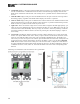
The Parts of a RAD
Following is an illustration of the front of a typical RAD, accompanied by descriptions of the RAD’s various hard-
ware features:
1. Label: a location on the RAD for inserting a custom label. One possible use of this label is to identify the
channel number associated with the corresponding jack.
2. XLR Tab: push tab for releasing a microphone cable. If you do not need this tab, you should remove it
before installing the RAD. For more information, see the RAD installation instructions beginning on page
1.
3. Input/Output jacks: the actual jacks to which you connect the appropriate audio device(s). The jacks
differ based on the RAD model.
4. Sig/OL LED: displays a green light when an audio signal is detected, displays a red light when the chan-
nel is experiencing a signal overload.
5. Power LED: displays a solid green when the RAD is receiving power, displays solid red if the voltage
received is lower than expected.
CHAPTER 2: Introduction to the HAL System
27