
Installation guide


Use these ports to connect each RAD to the HAL via a standard shielded CAT 5e (or better)cable. You
must use a shielded Ethernet cable for this connection. If you need more RAD connections, you will need
to connect an Expansion Unit with RAD ports (such as an EXP1) to your HAL device. You cannot con-
nect a RAD to a DR port.
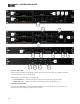
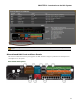
7. Digital Remote Device LEDs
Provides information about the health of the shielded CAT 5e connection between each DR and HAL.
The numbers correspond to the DR ports in the lower area of the rear panel. The Comm LED (on the top
row) lights solidly if the DR's data communications pair is working properly. The Power LED (on the bot-
tom row) lights solidly if HAL is supplying adequate power to the DR port.
8. Remote Audio Device LEDs
Provides status information about the health of the shielded CAT 5e connection between each RAD and
HAL. The numbers correspond to the RAD ports in the lower right corner of the rear panel. For example,
the LEDs for number 1 provide information about the RAD connected on port 1. Each LED corresponds
with one twisted pair within the shielded CAT 5e cable. If the twisted pair is functioning properly, the
LED displays a solid green light when the HAL is programmed to expect the RAD model that is phys-
ically plugged in. When all cable pairs are working properly, but HAL is not yet programmed for the con-
nected RAD model, all four LEDs flash red. Note that flashing red is a good thing: the cable’s good – just
program HAL and you’re done.
l
Audio Rx LED—lights solidly if the HAL receive pair is working properly.
l
Audio Tx LED—lights solidly if the HAL transmit pair is working properly.
l
Comm LED—lights solidly if the RAD's data communications pair is working properly.
l
Power LED—lights solidly if HAL is supplying adequate power to the RAD port.
NOTE: The Remote Audio Device LEDs on the front panel differ from those on the rear panel. The
front panel LEDs provide information about signal activity on each audio channel. See the "Over-
view of HAL Devices" on page 11 for more details.
TIP: You can use the Remote Audio Device LEDs on the rear panel and on the RAD to trou-
bleshoot connection problems.
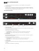
9. Relay Out ports
Reed relay ports used to signal another device. A common implementation is to link a relay port to a Tog-
gle control so that an end user can change its value. Also, the Halogen software contains a checkbox for
each relay port, the value of which you can include in a preset or link to another control, making it pos-
sible to use a preset or control to turn the relay port on or off.
10. Logic In ports
Use these TTL 5-volt digital logic input ports to communicate to the HAL System via an external control
device. You can configure each Logic In port to control a selector, toggle, or command within the HAL
System. For example, you might use a Logic In port to select between two audio channels, or to mute the
whole system.
11. Mic/Line Input ports
Use these ports to connect analog microphones or line input devices. Note that the Mic In ports support
phantom power.
12. Line Output ports
CHAPTER 2: Introduction to the HAL System
23