
Installation guide


These LEDs provide information on the following:
l
Overload LED (red) – indicates that the mic/line-plus input is experiencing a signal overload
l
Signal LED (green) – indicates the presence of an audio signal on the mic/line-plus input
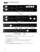
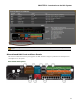
3. Line Output LEDs
Provides information about HAL analog outputs. The numbers correspond to the line output ports on the
rear panel.
These LEDs provide information on the following:
l
Overload LED (red) – indicates that the line output is experiencing a signal overload
l
Signal LED (green) – indicates the presence of an audio signal on the line output
4. Digital Remote LEDs
Indicates which Digital Remotes are enabled. Each numbered LED corresponds to the Digital Remote port
with the same number. If a Digital Remote is connected on a port but its Enabled LED is off, there is
likely a problem with the shielded CAT 5e connection or with the Digital Remote itself. If an Enabled
LED is flashing, it indicates that the physical Digital Remote model does not match the Digital Remote
model specified for this port in the HAL configuration.
5. Remote Audio Ports status indicators
Provides information about the RAD audio channels. The numbers at the top of the front panel correspond
to the RAD ports on the back of the HAL. For example, the LEDs for number 1 provide information
about the RAD connected on port 1.
Under each RAD number are LEDs for four audio channels, two input and two output. These four LEDs
represent the maximum number of channels a RAD is capable of transporting. However, not all RAD mod-
els use all four channels. For example, the RAD1 model provides two microphone inputs, so only the two
columns of indicators labeled IN would be active.
These LEDs provide information on the following:
l
Overload LED (red)–indicates that the channel is experiencing a signal overload
l
Signal LED (green)–indicates the presence of an audio signal on this channel
l
Enabled LED (yellow)–indicates the availability of the associated audio channel. If a RAD is con-
nected on this port and all Enabled lights are off, this indicates a problem with the shielded CAT
5e connection or with the RAD. If the Enabled LEDs are flashing, this indicates that the physical
RAD model does not match the RAD model specified for this port in the HAL configuration.
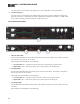
6. The Ethernet Comm and Link LEDs
Provides status information about the HAL Ethernet connection.
l
Comm LED (yellow) – flashes when HAL has been discovered by at least one PC running Rane-
Link II
1
, is solid when Halogen is exclusively connected to HAL, is off when HALhas yet to be
discovered.
l
Link LED (green) – indicates if the Ethernet network is connected. If the HAL is connected to an
Ethernet network but the Link LED is off, this indicates a problem with the connection.
7. The Expansion Bus LED
1
A service needed by Halogen to establish a connection with HAL.
CHAPTER 2: Introduction to the HAL System
17