
Installation guide


With the exception of the last item on this list (configuring emergency paging), the HALSystem Zone Proc-
essor streamlines all of these tasks and minimizes the hands-on configuration needed to get an output zone up
and running. At its simplest, all you need to do is drop a Zone Processor block into your system, wire in the
zone's local inputs, add optional post-processing, and connect to the appropriate output(s).
The Zone Processor automatically includes a connection to the Distributed Program Bus (which provides pre-
configured inputs to the zone), a connection to the paging system (including ducking), level control for the
zone, and source selection (although to provide remote control over the volume and selection, you need to
link to a DR or other remote device).
Although the HALSystem Zone Processor takes care of many tasks for you, there are typically a few things
you'll need to think about and configure. See the next question for a detailed discussion of the Zone Proc-
essor's contents and a closer look at how the Zone Processor works.
What does the Zone Processor do and what processing blocks are contained within it?
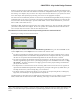
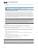
Following is an image of a Zone Processor block:
As you can see, it contains a blue box titled Distributed Program Bus and a green box titled Zone. It also
contains Input node(s) and an Output node. Let's examine each of these items:
l
The blue box indicates the automatic inclusion of connections to all inputs configured in the system's
Distributed Program Bus. If no Distributed Program Bus has been configured, that's okay. It just means
that there are no inputs from the Distributed Program Bus for the Zone Processor to include.
l
The green box indicates the automatic inclusion of connections to the paging system. In other words,
this zone automatically appears in the system's Paging Manager and is available for inclusion in a Pag-
ing Scenario
1
. All of the connections to the paging system as well as proper ducking are handled for
you by the Zone Processor.
l
The Input nodes in a Zone Processor are for connecting audio sources local to the zone (as opposed to
inputs from the Distributed Program Bus). Although only one Input node appears by default when you
first drag the block into your Processing Map, you can add more.
l
The block contains one Output node which you can connect to post-processing blocks, an Emergency
Page block, and ultimately to the appropriate final output block.
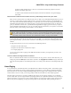
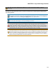
Contained inside the Zone Processor are additional processing blocks that you can configure. To access these
blocks, double-click the Zone Processor block. Following is an image of a Zone Processor's contents:
1
One or more paging zones treated as a group for paging purposes. Paging Scenarios are defined and named by the
designer, who then also assigns specific Scenarios to specific Paging Stations. End users always page into Sce-
narios.
CHAPTER 3: Key Audio Design Features
96