
Unit installation


Appendix D Command Language Installation and Operation Manual
D-30 Supervisory Terminal Commands FCD-E1
4. Select the desired parameters, and then press <Enter>.
If in step 3 the MAP MODE has been set to SEQ, FCD-E1 displays the time
and date fields, followed by the FCD-E1 prompt.
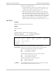
If the MAP MODE has been set to USER, after you press <Enter> you will
see the first line of the sub timeslot map of the sublink. A typical display is
shown below:
TS : NO 01 NO 02 NO 03 NO 04 NO 05 NO 06 NO 07
: NC NC NC NC NC NC NC
Use the spacebar to move between timeslots. For each timeslot:
Select among VOICE, DATA (voice, respectively data timeslot allocated
to the sublink), or NC (not connected) by pressing <F> or <B>.
After completing the first line, press <Enter> to continue to the next
line. Repeat the procedure until all the timeslots are defined. The
maximum number of timeslots is 31.
5. When done, press <Enter> to end.
DEF SP
Purpose
Define the supervisory port parameters. Refer to Table D-3 for the parameter
description, allowable ranges and configuration guidelines.
Syntax
DEF SP
Use
1. To define the supervisory port parameters, type:
DEF SP<Enter>
The first line of the supervisory port parameters data form is displayed. A
typical form is shown below.
SPEED DATA PARITY INTERFACE CTS DCD_DEL DSR
AUTO 8 NO DCE =RTS 0 MS ON
2. Change the desired parameters and press <Enter> to display the next line:
POP_ALM PWD LOG_OFF CALL_OUT_TRIGER
ACTIVATE_CALL_OUT AUXILIARY_DEVICE
NO NO NO NONE ANY CASE
TERMINAL
3. When done, press <Enter> to end.
Table D-11 describes additional parameters of the supervisory port available only
through the supervisory terminal.