
Unit installation


Chapter 5 Configuring Typical Applications Installation and Operation Manual
5-2 Configuration Example FCD-E1
Table 5-1. Outline of Configuration Procedures (Cont.)
Step Activity Reference
5 Define the general system parameters DEF AGENT
DEF MANAGER LIST
DEF ROUTE
DEF NAME
DEF PROMPT
DEF PWD
6 Define dial-up parameters (when applicable) DEF CALL
Define alarm handling parameters DEF ALM MASK
DEF AP
DEF AR
5.3 Configuration Example
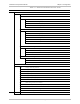
This section illustrates the procedure details for configuring two FCD-E1 units,
using a supervision terminal, for a typical application (see Figure 5-1).
In this application, two FCD-E1 units, each having one data channel and a sublink,
are interconnected via the E1 network and managed by a RADview network
management station attached to a DXC unit. The data channel rate is 128 kbps,
the number of voice channels to be connected between the two PBXs is 10, and
the management station is connected to both FCD-E1 units via the main links.
DXC
Radio
Station
Router
E1 Network
FCD-E1
128 kbps
V.35
PBX
FCD-E1
128 kbps
V.35
PBX
Figure 5-1. FCD-E1 Application for Configuration Examples Interconnected by an
E1 Network