
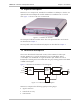
- RAD Data Communication Fiber Optic Modem Installation and Operation Manual E1, T1


FOM-E1/T1 Installation and Operation Manual i
Contents
Chapter 1. Introduction
1.1
Overview..................................................................................................................... 1-1
Versions................................................................................................................................1-1
Application ...........................................................................................................................1-2
Features................................................................................................................................1-2
1.2
Physical Description..................................................................................................... 1-3
1.3
Functional Description................................................................................................. 1-3
Signal Conversion ................................................................................................................. 1-4
Data/Clock Recovery ............................................................................................................1-4
Data Transfer........................................................................................................................ 1-4
1.4
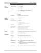
Technical Specifications............................................................................................... 1-5
Chapter 2. Installation and Setup
2.1
Site Requirements and Prerequisites ............................................................................ 2-1
2.2
Package Contents ........................................................................................................ 2-1
2.3
Installation and Setup .................................................................................................. 2-2
Configuring FOM-E1/T1........................................................................................................2-2
Connecting the Interfaces .....................................................................................................2-4
Connecting the Power ..........................................................................................................2-5
Chapter 3. Operations
3.1
Front Panel Controls and Indicators ............................................................................. 3-1
3.2
Operating Instructions ................................................................................................. 3-2
Turning On...........................................................................................................................3-2
Normal Operating Instructions ..............................................................................................3-2
Turning Off...........................................................................................................................3-2
Chapter 4. Testing and Diagnostics
4.1
Status Indicators and Alarm Relay ................................................................................ 4-1
Front Panel LEDs ..................................................................................................................4-1
Alarm Relay ..........................................................................................................................4-1
4.2
Diagnostic Tests ........................................................................................................... 4-2
Local Analog Loopback (LLB) ................................................................................................4-2
Remote Digital Loopback (RLB).............................................................................................4-2
4.3
Troubleshooting Instructions ........................................................................................ 4-3
4.4
Frequently Asked Questions ........................................................................................ 4-4
Chapter 5. FOM-E1/T1/R Card Version
5.1
ASM-MN-214 Card Cage............................................................................................. 5-1
5.2
Power Supply .............................................................................................................. 5-2
AC Supply ............................................................................................................................5-2
DC Supply............................................................................................................................5-3
Power Supply Redundancy ...................................................................................................5-3
5.3
FOM-E1/T1/R Front Panel............................................................................................ 5-4