Installation and Operation Manual FOM-E1/T1 E1/T1 Fiber Optic Modem
FOM-E1/T1 E1/T1 Fiber Optic Modem Installation and Operation Manual Notice This manual contains information that is proprietary to RAD Data Communications Ltd. ("RAD"). No part of this publication may be reproduced in any form whatsoever without prior written approval by RAD Data Communications.
Limited Warranty RAD warrants to DISTRIBUTOR that the hardware in the FOM-E1/T1 to be delivered hereunder shall be free of defects in material and workmanship under normal use and service for a period of twelve (12) months following the date of shipment to DISTRIBUTOR.
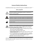
General Safety Instructions The following instructions serve as a general guide for the safe installation and operation of telecommunications products. Additional instructions, if applicable, are included inside the manual. Safety Symbols Warning This symbol may appear on the equipment or in the text. It indicates potential safety hazards regarding product operation or maintenance to operator or service personnel.
Handling Energized Products General Safety Practices Do not touch or tamper with the power supply when the power cord is connected. Line voltages may be present inside certain products even when the power switch (if installed) is in the OFF position or a fuse is blown. For DC-powered products, although the voltages levels are usually not hazardous, energy hazards may still exist.
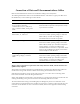
Connection of Data and Telecommunications Cables Data and telecommunication interfaces are classified according to their safety status. The following table lists the status of several standard interfaces. If the status of a given port differs from the standard one, a notice will be given in the manual. Ports Safety Status V.11, V.28, V.35, V.36, RS-530, X.
Caution Attention To reduce the risk of fire, use only No. 26 AWG or larger telecommunication line cords. Pour réduire les risques s’incendie, utiliser seulement des conducteurs de télécommunications 26 AWG ou de section supérieure. Some ports are suitable for connection to intra-building or non-exposed wiring or cabling only. In such cases, a notice will be given in the installation instructions. Do not attempt to tamper with any carrier-provided equipment or connection hardware.
Canadian Emission Requirements This Class A digital apparatus meets all the requirements of the Canadian Interference-Causing Equipment Regulation. Cet appareil numérique de la classe A respecte toutes les exigences du Règlement sur le matériel brouilleur du Canada. Warning per EN 55022 (CISPR-22) Warning This is a class A product. In a domestic environment, this product may cause radio interference, in which case the user will be required to take adequate measures.
Declaration of Conformity Manufacturer's Name: RAD Data Communications Ltd. Manufacturer's Address: 24 Raoul Wallenberg St. Tel Aviv 69719 Israel declares that the product: FOM-E1/T1 Product Name: conforms to the following standard(s) or other normative document(s): EMC: Safety: EN 55022 (1994) Limits and methods of measurement of radio disturbance characteristics of information technology equipment.
Quick Start Guide Installation of FOM-E1/T1 should be carried out only by an experienced technician. If you are familiar with FOM-E1/T1, use this quick start guide to set it up for operation. This guide describes the standalone version of the modem. Perform the installation procedures for both the local and the remote units. 1. Installing FOM-E1/T1 Configuring FOM-E1/T1 1. Open the modem’s case. 2. Select the E1/T1 electrical interface (JP2, JP4, JP5, JP6, JP7 and JP8). 3.
FOM-E1/T1 Installation and Operation Manual Quick Start Guide Connecting the Cables To connect cables: 1. Connect the E1/T1 electrical interface. 2. Connect the fiber optic interface. 3. Connect the power cable (first to the modem, then to the mains). Operation starts when the power is applied to the rear panel power connector. 2. Operating FOM-E1/T1 1. Check that the TEST switch is set to the NORM position. 2. Verify LED status. All the LED indicators should be OFF, except for the PWR indicator. 3.
Contents Chapter 1. Introduction 1.1 Overview..................................................................................................................... 1-1 Versions................................................................................................................................ 1-1 Application ........................................................................................................................... 1-2 Features........................................................
Table of Contents 5.4 Installing the FOM-E1/T1/R Card ................................................................................. 5-5 Setting Internal Jumpers and Switches ................................................................................... 5-5 Installing FOM-E1/T1/R into the ASM-MN-214 Card Cage..................................................... 5-6 Connecting the Interfaces .....................................................................................................
Chapter 1 Introduction 1.1 Overview This manual provides information on the technical characteristics, installation and operation of the FOM-E1/T1 fiber optic modem as a standalone unit, and as FOM-E1/T1/R rack-mount card for the ASM-MN-214 modem rack. FOM-E1/T1 is a fiber optic modem for transmission of E1 (2.048 Mbps) or T1 (1.544 Mbps) over multimode or single-mode fiber optic media. The communication equipment is connected to FOM-E1/T1 according to the ITU G.703 standard.
FOM-E1/T1 Installation and Operation Manual Chapter 1 Introduction Application In the application illustrated, each FOM-E1/T1 receives E1 or T1 signals that are equalized to overcome electrical link distortion. FOM-E1/T1 then converts the E1 or T1 signals into an optical signal. E1/T1 E1/T1 Coax Fiber Optic FOM-E1/T1 PBX E1/T1 FOM-E1/T1 Coax DACS Figure 1-1 FOM-E1/T1 Application Features Fiber Optic Interface Table 1-1 details fiber optic interface types supported by FOM-E1/T1. Table 1-1.
FOM-E1/T1 Installation and Operation Manual Chapter 1 Introduction 1.2 Physical Description FOM-E1/T1 is a compact unit, intended for installation on desktops or shelves. An optional rack-mount adapter kit enables FOM-E1/T1 installation into a 19-inch rack. Figure 1-2 shows a 3D view of FOM-E1/T1. Figure 1-2 FOM-E1/T1 3D View The front panel indicates modem status. The front panel indicators and controls are described in Chapter 3.
Chapter 1 Introduction FOM-E1/T1 Installation and Operation Manual Signal Conversion Conversion of the electrical signal into an optical signal takes place by using an infrared light-emitting diode or laser transmitter. At the opposite end of the fiber, the optical signal is converted back into an electrical signal and amplified to the required level. Data/Clock Recovery To recover data and clock from the signal, a Phase Locked Loop (PLL) circuit is utilized.
FOM-E1/T1 Installation and Operation Manual Chapter 1 Introduction 1.4 Technical Specifications E1/T1 Interface Transmission Rates E1: 2.048 Mbps T1: 1.
FOM-E1/T1 Installation and Operation Manual Chapter 1 Introduction Physical Height Power 44 mm / 1.7 in (1U) Width 179 mm / 7.0 in Depth 203 mm / 8.0 in Weight 1.1 kg / 3.0 lb AC Voltage 115 or 230 VAC (±10%), 50 or 60 Hz, 6W DC Voltage 24 VDC (18 to 36 VDC) or -48 VDC (-36 to -72 VDC) Fuses FOM-E1/T1: • 115 VAC supply: 0.2A T 250V • 230 VAC supply: 0.
Chapter 2 Installation and Setup This chapter describes installation and setup procedures for the standalone FOM-E1/T1 modem. FOM-E1/T1 is delivered completely assembled. It is designed for tabletop or 19-inch rack installation. For instructions on installation of a single unit or two units in a 19-inch rack, refer to the rack mounting kit for 19-inch racks guide that comes with the RM kit. After installing the unit, refer to Chapter 3 to assure normal operation.
Chapter 2 Installation and Setup FOM-E1/T1 Installation and Operation Manual 2.3 Installation and Setup FOM-E1/T1 is a standalone device intended for tabletop or bench installation. It is delivered completely assembled. No provision is made for bolting the unit on the tabletop. To install FOM-E1/T1: 1. Determine the required configuration of FOM-E1/T1 and set the internal jumpers accordingly (see Configuring FOM-E1/T1 below). 2. Connect the line (see Connecting the Fiber Optic Interface below). 3.
FOM-E1/T1 Installation and Operation Manual Chapter 2 Installation and Setup Setting the SW1 and SW2 switches to CONNECTED is valid for coaxial cables only. When using 4-wire connection, set these switches to FLOATING. Note 5. Slide the PCB interior back into the case. 6. Screw in the two rear panel screws to secure the PCB in the case. Now you can proceed with the line, DTE and power connections as described below.
FOM-E1/T1 Installation and Operation Manual Chapter 2 Installation and Setup Table 2-1 FOM-E1/T1 Internal Jumpers and Switches Jumper/Switch Function Possible Settings Factory Setting SW3, AIS When a major alarm is detected, AIS is transmitted to either the electrical or optical interface.
FOM-E1/T1 Installation and Operation Manual Chapter 2 Installation and Setup 2. Connect the transmit fiber to the connector marked TX and the receive fiber to the connector marked RX. 3. At the remote unit connect the transmit fiber to RX and the receive fiber to TX. Connecting the E1/T1 Interface The rear-panel E1/T1 connector provides interface for data input/output, clock reference and control signal exchange between FOM-E1/T1 and E1/T1 equipment.
Chapter 2 Installation and Setup FOM-E1/T1 Installation and Operation Manual Connecting AC Power AC power should be supplied to FOM-E1/T1 through the 1.5m (5 ft) standard power cable terminated by a standard 3-prong plug. The cable is provided with the unit. To connect AC power: 1. Connect the power cable to the power connector on the FOM-E1/T1 rear panel. 2. Connect the power cable to the mains outlet. The unit will be turned on automatically upon connection to the mains.
Chapter 3 Operations This chapter provides the following information for the FOM-E1/T1 standalone modem: • FOM-E1/T1 front-panel indicators and controls • Operating procedures (turn-on, front-panel indications, performance monitoring and turn-off). • Installation procedures given in Chapter 2 must be completed and checked before attempting to operate FOM-E1/T1. 3.1 Front Panel Controls and Indicators Figure 3-1 shows the FOM-E1/T1 front panel. Table 3-1 lists the FOM-E1/T1 controls and indicators.
Chapter 3 Operations FOM-E1/T1 Installation and Operation Manual 3.2 Operating Instructions Turning On FOM-E1/T1 starts operating as soon as it is connected to the power source. The PWR LED turns ON and remains lit as long as the units are connected to the mains. Normal Operating Instructions During normal operation all indicators should be OFF, except for the PWR indicator.
Chapter 4 Testing and Diagnostics This chapter describes the FOM-E1/T1 diagnostics functions, which include: • Front panel LED indicators • Alarm relay • Diagnostic loopbacks. In addition, this chapter provides some tips on troubleshooting and frequently asked questions. 4.1 Status Indicators and Alarm Relay Front Panel LEDs The status of FOM-E1/T1 is indicated by the front panel LED indicators. For description of LED indicators and their functions, refer to Chapter 3.
FOM-E1/T1 Installation and Operation Manual Chapter 4 Testing and Diagnostics 4.2 Diagnostic Tests Local Analog Loopback (LLB) FOM-E1/T1 supports activation of a local loopback, which tests the performance of the E1/T1 electrical interface of the local unit and equipment attached to it. The data received at the E1/T1 electrical interface is looped back to the equipment attached to it (see Figure 4-1). LOC Position Coax FOM-E1/T1 E1 or T1 BERT Figure 4-1.
FOM-E1/T1 Installation and Operation Manual Chapter 4 Testing and Diagnostics 4.3 Troubleshooting Instructions Table 4-2 provides troubleshooting details. Perform the actions listed under Corrective Measures in the order given in the table, until the problem is corrected. Table 4-2. Troubleshooting Chart Symptom Probable Cause(s) Corrective Measures PWR LED is OFF No AC power Verify that the power outlet is providing the required power.
Chapter 4 Testing and Diagnostics FOM-E1/T1 Installation and Operation Manual 4.4 Frequently Asked Questions Q: Does FOM-E1/T1 operate opposite FOM-40? A: No. The fiber optic interfaces of these modems are not compatible. Q: Can I connect FOM-E1/T1 with a balanced interface to FOM-E1/T1 with an unbalanced interface? A: Yes Q: What is the maximal distance between FOM-E1/T1 and end equipment (E1 link)? A: The FOM-E1/T1 output conforms to the G.
Chapter 5 FOM-E1/T1/R Card Version This chapter describes the card cage version of FOM-E1/T1. It discusses the following topics: • ASM-MN-214 card cage • FOM-E1/T1/R plug-in card for the ASM-MN-214 cage • Cage and card power supply • Installation of cage and card. 5.1 ASM-MN-214 Card Cage The ASM-MN-214 card cage contains one or two power supplies and up to 14 plug-in cards. The card types can be FOM-E1/T1/R or other RAD rack version modems/converters – any combination of up to 14 plug-in cards.
FOM-E1/T1 Installation and Operation Manual Chapter 5 FOM-E1/T1/R Card Version Terminal Block Terminal Block CIA/TB-BNC/214 Figure 5-1 ASM-MN-214 Rear Panel 5.2 Power Supply The FOM-E1/T1/R card is powered from the ASM-MN-214 power supply via its chassis. Each FOM-E1/T1/R card has two fuses that protect the entire system against power failure due to a short circuit in one card (see Figure 5-4). The ratings of the fuses are 1A, 250V and 50 mA 250V.
FOM-E1/T1 Installation and Operation Manual Chapter 5 FOM-E1/T1/R Card Version DC Supply The DC power supply is -48 VDC (-36 to -72 VDC) or 24 VDC (18 to 32 VDC). It uses a DC/DC converter module to provide the power required for the cards. Power Supply Redundancy This special ordering option is equipped with two separate power supplies, operating together and sharing the load of the whole card cage. If either of the power supplies fails, the other one will continue to supply power to the full card cage.
FOM-E1/T1 Installation and Operation Manual Chapter 5 FOM-E1/T1/R Card Version 5.3 FOM-E1/T1/R Front Panel Figure 5-3 shows the FOM-E1/T1/R card front panel. The front panel of FOM-E1/T1/R includes fiber optic connectors, loopback initiation switch and LED indicators. The front panel LEDs of the card version are identical in their functionality to those of the standalone device. For this information, refer to the Front Panel Controls and Indicators section in Chapter 3.
FOM-E1/T1 Installation and Operation Manual Chapter 5 FOM-E1/T1/R Card Version 5.4 Installing the FOM-E1/T1/R Card Setting Internal Jumpers and Switches The FOM-E1/T1/R internal jumpers and switches are similar in their functionality to those of the standalone unit, as detailed Table 5-1. Figure 5-4 illustrates the FOM-E1/T1/R PCB layout.
Chapter 5 FOM-E1/T1/R Card Version FOM-E1/T1 Installation and Operation Manual Table 5-1. FOM-E1/T1/R Internal Jumpers and Switches Jumper/Switch Function Possible Settings Factory Setting SW4, AIS When a major alarm is detected, AIS is transmitted to either the electrical or optical interface.
Appendix A Interface Connector Specifications A.1 Standalone FOM-E1/T1 DB-15 Connector Balanced E1/T1 interface terminates in DB-15 female connector, which also serves as an alarm relay. Table A-1 describes the DB-15 pins that serve for the E1/T1 connection. Table A-2 describes the DB-15 pins that serve for the alarm relay. Table A-1.
FOM-E1/T1 Installation and Operation Manual Appendix A Interface Connector Specifications CBL-E1T1/RJ45 Cable RAD offers an optional splitter cable, CBL-E1T1/RJ45, which connects the DB-15 female connector of the standalone unit to the balanced E1/T1 device and alarm equipment. The CBL-E1T1/RJ45 cable includes two DB-15 connectors (male and female) and one RJ-45 connector. Figure A-1 illustrates the cable schematics.
24 Raoul Wallenberg St., Tel Aviv 69719, Israel Tel: +972-3-6458181, Fax: +972-3-6483331, +972-3-6498250 E-mail: erika_y@rad.co.il , Web site: www.rad.com Customer Response Form RAD Data Communications would like your help in improving its product documentation. Please complete and return this form by mail or by fax or send us an e-mail with your comments.
Error Report Type of Error(s) ❒ Incompatibility with product or Problem(s): ❒ Difficulty in understanding text ❒ Regulatory information (Safety, Compliance, Warnings, etc.) ❒ Difficulty in finding needed information ❒ Missing information ❒ Illogical flow of information ❒ Style (spelling, grammar, references, etc.) ❒ Appearance ❒ Other _________ Please list the exact page numbers with the error(s), detail the errors you found (information missing, unclear or inadequately explained, etc.
www.rad.com INTERNATIONAL HEADQUARTERS: 24 Raoul Wallenberg Street, Tel Aviv 69719, Israel, Tel: 972-3-6458181 Fax: 972-3-6498250, 972-3-6474436, Email: rad@rad.co.il U.S. HEADQUARTERS: 900 Corporate Drive, Mahwah, N.J. 07430, Tel: (201) 529-1100 Toll Free: 1-800-444-7234, Fax: (201) 529-5777, Email: market@radusa.com Publication No.