
Specifications


Installing RIC-E1 1
Quick Start Guide
If you are familiar with RIC-E1, use this guide to prepare it for operation.
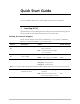
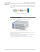
1. Installing RIC-E1
Open the RIC-E1 case by sliding the blue side panel forward and releasing the two
screws located on the bottom panel at the rear end of the unit.
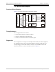
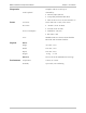
Setting the Internal Jumpers
Set the internal jumpers. Refer the first table below, if you operate a standalone
RIC-E1, or to the second table, if you use RIC-E1/R.
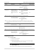
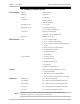
Jumper Description Values Default Setting
JP1, JP2, JP3, JP4,
JP6
Select the E1 interface type BAL – Balanced interface
(RJ-45 connector)
BNC – Unbalanced interface (BNC
coax connectors)
BAL
TX & RX CODE,
JP9
Selects the transmit and
receive coding
AMI – Jumper plug is installed
HDB3 – Jumper plug is not installed
HDB3
TIMING, J4 Selects the clock reference RCV (pin 4) – Receive clock
EXT (pin 5) – External clock
INT (pin 6) – Internal clock
RCV
Note: Units with the IR-ETH, IR-ETH/QN and IR-IP interface modules support only receive and internal clocks.
ANA LOOP, JP11 Controls the local analog
loopback activation
LOC – Activates the local analog
loopback
DTE – Allows the activation of the
local analog loopback via DTE
DTE