Installation and Operation Manual RIC-E1 E1 Interface Converter
RIC-E1 E1 Interface Converter Installation and Operation Manual Notice This manual contains information that is proprietary to RAD Data Communications Ltd. ("RAD"). No part of this publication may be reproduced in any form whatsoever without prior written approval by RAD Data Communications.
Limited Warranty RAD warrants to DISTRIBUTOR that the hardware in the RIC-E1 to be delivered hereunder shall be free of defects in material and workmanship under normal use and service for a period of twelve (12) months following the date of shipment to DISTRIBUTOR.
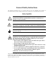
General Safety Instructions The following instructions serve as a general guide for the safe installation and operation of telecommunications products. Additional instructions, if applicable, are included inside the manual. Safety Symbols Warning This symbol may appear on the equipment or in the text. It indicates potential safety hazards regarding product operation or maintenance to operator or service personnel.
Handling Energized Products General Safety Practices Do not touch or tamper with the power supply when the power cord is connected. Line voltages may be present inside certain products even when the power switch (if installed) is in the OFF position or a fuse is blown. For DC-powered products, although the voltages levels are usually not hazardous, energy hazards may still exist.
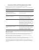
Connection of Data and Telecommunications Cables Data and telecommunication interfaces are classified according to their safety status. The following table lists the status of several standard interfaces. If the status of a given port differs from the standard one, a notice will be given in the manual. Ports Safety Status V.11, V.28, V.35, V.36, RS-530, X.
Caution Attention To reduce the risk of fire, use only No. 26 AWG or larger telecommunication line cords. Pour réduire les risques s’incendie, utiliser seulement des conducteurs de télécommunications 26 AWG ou de section supérieure. Some ports are suitable for connection to intra-building or non-exposed wiring or cabling only. In such cases, a notice will be given in the installation instructions. Do not attempt to tamper with any carrier-provided equipment or connection hardware.
Canadian Emission Requirements This Class A digital apparatus meets all the requirements of the Canadian Interference-Causing Equipment Regulation. Cet appareil numérique de la classe A respecte toutes les exigences du Règlement sur le matériel brouilleur du Canada. Warning per EN 55022 (CISPR-22) Warning This is a class A product. In a domestic environment, this product may cause radio interference, in which case the user will be required to take adequate measures.
Declaration of Conformity Manufacturer's Name: RAD Data Communications Ltd. Manufacturer's Address: 24 Raoul Wallenberg St. Tel Aviv 69719 Israel declares that the products: Product Names: RIC-E1, RIC-T1 conform to the following standard(s) or other normative document(s): EMC: Safety: EN 55022: 1998 Information technology equipment – Radio disturbance characteristics – Limits and methods of measurement.
Quick Start Guide If you are familiar with RIC-E1, use this guide to prepare it for operation. 1. Installing RIC-E1 Open the RIC-E1 case by sliding the blue side panel forward and releasing the two screws located on the bottom panel at the rear end of the unit. Setting the Internal Jumpers Set the internal jumpers. Refer the first table below, if you operate a standalone RIC-E1, or to the second table, if you use RIC-E1/R.
RIC-E1 Installation and Operation Manual Quick Start Guide Jumper Description Values Default Setting JP2, JP3 Select the E1 interface type BALANCE – Balanced interface (RJ-45 connector) BALANCE UNBALANCE – Unbalanced interface (BNC coax connectors) ALB DTE, JP4 Enables local analog loopback activation from the DTE (via pin 18 for RS-530 or via pin “JJ” for V.
Contents Chapter 1. Introduction 1.1 Overview..................................................................................................................... 1-1 Versions................................................................................................................................ 1-1 Application ........................................................................................................................... 1-2 1.2 Physical Description.......................................
Table of Contents Appendix A. Interface Connector Wiring Appendix B. IR-ETH Interface Module Appendix C. IR-ETH/QN Interface Module Appendix D. IR-IP Interface Module Appendix E. IR-X.21B Interface Module List of Figures 1-1. Typical Application................................................................................................................ 1-2 1-2. RIC-E1 and RIC-T1, 3D View ................................................................................................ 1-2 1-3.
Chapter 1 Introduction 1.1 Overview RIC-E1 is an interface converter. It converts unframed HDB3 or AMI data of ITU G.703 E1 balanced or unbalanced interface into an interchangeable DTE interface module. RIC-E1 operates at 2048 kbps. It extracts data and the clock from the G.703 interface via a jitter attenuator to meet ITU G.823 requirements. RIC-E1 acts as a line transceiver. It provides protection from over-voltage and over-current stress caused by lightning, power crosses and other noise sources.
RIC-E1 Installation and Operation Manual Chapter 1 Introduction Application RIC-E1 is typically used to connect between a G.703 network and a DTE. The DTE can be a multiplexer, a bridge, a router etc. Figure 1-1 illustrates a typical RIC-E1 application. Network G.703 V.35 RIC-E1 DTE Figure 1-1. Typical Application 1.2 Physical Description A three-dimensional view of RIC-E1 and RIC-T1 is shown in Figure 1-2. Figure 1-2.
RIC-E1 Installation and Operation Manual Chapter 1 Introduction 1.3 Functional Description Functional Block Diagram Figure 1-3 shows the functional block diagram of RIC-E1. X Unbalanced Txd Transformers Interchangable Interfaces Rxd Txclk Rxclk Balanced Select IMP Unbalanced LIU Loss BNC RJ - 45 BNC Tx & Rx Code Tst Ana Clock Gen. AMI HDB3 P.S. Figure 1-3.
RIC-E1 Installation and Operation Manual Chapter 1 Introduction 1.4 Technical Specifications Link Interface Coding HDB3 or AMI Framing Unframed Bit Rate 2.048 Mbps Impedance 120Ω, balanced 75Ω, unbalanced RCV Signal Level 0 to -10 dB XMT Signal Level 3V (±10%), balanced 2.37V (±10%), unbalanced Connectors RJ-45, 8-pin, balanced Two BNC coaxial, unbalanced DTE Interface Return Loss Better than 15 dB Type • V.35: 34-pin, female • X.21: 15-pin, D-type female • V.
RIC-E1 Installation and Operation Manual Chapter 1 Introduction Complies with ITU V.54 (loop 3) Diagnostics Local Loopback Activated by: • Internal jumper (RIC-E1) • Front panel pushbutton (RIC-E1/R) • DTE circuit 141 for V.35, RS-530 and V.36 Power AC Source 100 to 240 VAC (± 10%), 50 or 60 Hz DC Source • -48 VDC (-42 to -60 VDC) • 24 VDC (18 to 32 VDC) Power Consumption • Standalone: 3W, max • RIC-E1/R: 5.
Chapter 1 Introduction 1-6 Technical Specifications RIC-E1 Installation and Operation Manual
Chapter 2 Installation and Setup This chapter explains how to configure and install RIC-E1. After the installation is complete, refer to Chapter 3 for information about operating RIC-E1. Refer to Chapter 4 for troubleshooting and diagnostics information. 2.1 Site Requirements and Prerequisites AC-powered RIC-E1 units should be installed within 1.5m (5 ft) of an easily-accessible grounded AC outlet capable of furnishing the required supply voltage, in the range of 100 to 240 VAC.
Chapter 2 Installation and Setup RIC-E1 Installation and Operation Manual 2.3 Configuring RIC-E1 This section provides information on the functions and locations of RIC-E1 internal jumpers. Use this information to select the correct setting for your particular application. To install RIC-E1: 1. Determine the required configuration, according to your application, and set the internal jumpers accordingly. For more information, refer to Setting the Jumpers on page 2-2. 2. Connect the DTE and G.
RIC-E1 Installation and Operation Manual JP1 JP2 JP3 JP4 Chapter 2 Installation and Setup BAL BNC BAL BNC RCV EXT INT JP6 J4 TX & RX CODE AMI JP9 HDB3 JP11 LOC DTE ANA LOOP Figure 2-1. RIC-E1 Jumper Locations Table 2-1.
RIC-E1 Installation and Operation Manual Chapter 2 Installation and Setup Selecting the Impedance When RIC-E1 uses the balanced interface: • Terminate the impedance of G.703 link to 120Ω. • Use only the RJ-45 connector to transmit full duplex data to the G.703 network over UTP or STP cable. When RIC-E1 uses the unbalanced interface: • Terminate the impedance of G.703 link to 75Ω. • Use only the coaxial BNC connectors to transmit to the G.703 network via two coaxial cables.
RIC-E1 Installation and Operation Manual Chapter 2 Installation and Setup Connecting the DTE RIC-E1 supports various types of data channel interfaces. Equipment with V.35, X.21, RS-530 and Ethernet interfaces can be connected directly to the RIC-E1 DTE port. The RIC-E1 V.36 interface is provided via an adapter cable converting between 25-pin RS-530 connector and 37-pin V.36 connector. Connector pin allocations and cable wiring data appear in Appendix A.
Chapter 2 Installation and Setup 2-6 Configuring RIC-E1 RIC-E1 Installation and Operation Manual
Chapter 3 Operation This chapter describes how to operate RIC-E1. Installation procedures explained in Chapter 2 must be completed and checked before attempting to operate RIC-E1. 3.1 Front Panel Indicators Figure 3-1 shows the RIC-E1 front panel. The front panel indicators are described in Table 3-1. Figure 3-1. RIC-E1 Front Panel Table 3-1.
Chapter 3 Operation RIC-E1 Installation and Operation Manual 3.2 Operating Instructions Turning On RIC-E1 starts operating as soon as AC or DC power is connected. Always connect the power cable to the RIC-E1 power connector first and then to the mains outlet. The PWR LED lights when power is connected. Operating RIC-E1 RIC-E1 operates entirely unattended except when performing system tests. Turning Off To turn RIC-E1 off, disconnect the power cable from the mains outlet.
Chapter 4 Troubleshooting and Diagnostics 4.1 Performing Local Analog Loopback RIC-E1 supports activation of a V.54 diagnostic (loop 3) local loopback. This loopback checks the communication and connection between RIC-E1 and the attached DTE, as shown in Figure 4-1. When RIC-E1 performs a local loopback, the data received from the local transmitter is both transmitted on the line and looped back to the local receiver at the digital level. This checks the operation of all local digital circuitry.
Chapter 4 Troubleshooting and Diagnostics RIC-E1 Installation and Operation Manual To activate the local analog loopback from the standalone RIC-E1: 1. Open the RIC-E1 case, as described in Chapter 2. 2. Set the JP11 jumper to LOC. The analog loopback is activated and the TST indicator on the front panel turns on. To activate the local analog loopback from RIC-E1/R: • Press the ANA pushbutton on the RIC-E1/R front panel. Make sure that the PNL SW jumper (JP5) on the RIC-E1/R board is set to EN.
Chapter 5 RIC-E1/R Card This chapter describes the RIC-E1/R card version, designed for installation in the ASM-MN-214 card cage. The chapter contains the following sections: • The ASM-MN-214 card cage • The RIC-E1/R card version • Power supply to RIC-E1/R card • Installing the RIC-E1/R card. 5.1 ASM-MN-214 Card Cage The ASM-MN-214 card cage contains one or two power supplies and up to 14 plug-in cards.
RIC-E1 Installation and Operation Manual Chapter 5 RIC-E1/R Card RIC-E1/R with one of the Ethernet interfaces (IR-ETH, IR-ETH/QN or IR-IP) uses a CIA/ETH interface adapter, which converts one DB-25 connector to an RJ-45 connector. The adapter cable and interface attachments are also shown in Figure 5-1. Terminal Block Terminal Block CIA/TB-BNC/214 CIA/V.35/1 CIA/X.21/1 CIA/ETH CBL-530/449 Figure 5-1.
RIC-E1 Installation and Operation Manual Chapter 5 RIC-E1/R Card 5.2 Power Supply Power is supplied to the RIC-E1/R card from the ASM-MN-214 power supply via the chassis. Each RIC-E1/R card has two fuses (F5 and F6), which protect the entire system against power failure resulting from a short circuit in one card. The rating of the fuses is 500 mA, 250V, slowblow (see Figure 5-6). The ASM-MN-214 card cage can accept both AC or DC power supplies.
RIC-E1 Installation and Operation Manual Chapter 5 RIC-E1/R Card 5.3 RIC-E1/R Front Panel Figure 5-2, Figure 5-3 and Figure 5-4 show the RIC-E1/R card front panel options. The LEDs of the card version with serial DTE interface are identical in their functionality to those of the standalone device, except for the ANA pushbutton. The ANA pushbutton serves for activation of the local analog loopback, see Chapter 4 for the details.
RIC-E1 Installation and Operation Manual Chapter 5 RIC-E1/R Card Figure 5-5.
RIC-E1 Installation and Operation Manual Chapter 5 RIC-E1/R Card 5.4 Installing the RIC-E1/R Card Setting Internal Jumpers and Switches JP2 Figure 5-6 illustrates location of the internal jumpers on the RIC-E1/R PCB. BALANCE UNBALANCE JP3 BALANCE UNBALANCE J2 DIS ALB DTE DIS PNL SW JP5 EN JP4 EN INT EXT RCV TIMING SEL B8ZS/ HDB3 AMI JP6 TX&RX CODE CON J3 CHASS-GND DISCON F5 F6 Figure 5-6 RIC-E1/R PCB Layout Table 5-1.
RIC-E1 Installation and Operation Manual Chapter 5 RIC-E1/R Card Table 5-1. RIC-E1/R Jumper Settings (Cont.) Jumper Description Values Default Setting PNL SW, JP5 Enables activation of the local analog loopback via the front panel pushbutton EN – The LLB can be activated via the front panel EN DIS – The LLB cannot be activated via the front panel Note: The JP5 jumper is not available for RIC-E1/R cards with IR-ETH and IR-ETH/QN interface modules.
RIC-E1 Installation and Operation Manual Chapter 5 RIC-E1/R Card 4. When operating RIC-E1/R with unbalanced interface, use CIA/TB-BNC/214 adapter, which converts the terminal block connector into two coaxial BNC connectors. 5. If required, attach the appropriate CIA (CIA/X.21/1, CIA/V.35/1, CIA/ETH) or CBL-530/449F adapter cable to the DB-25 connector on the card cage rear panel. 6.
Appendix A Interface Connector Wiring A.1 V.35, X.21 and RS-530 Interface Connectors Table A-1 lists the pin assignments of the V.35, X.21 and RS-530 interface connectors. Table A-1. V.35, X.21 and RS-530 Interfaces, Pin Assignments V.35, 34-Pin Signal Function Pin RS-530, DB-25 Circuit Pin X.
RIC-E1 Installation and Operation Manual Appendix A Interface Connector Wiring Table A-1. V.35, X.21 and RS-530 Interfaces, Pin Assignments (Cont.) V.35, 34-Pin Signal Function Pin RS-530, DB-25 Circuit Pin X.
RIC-E1 Installation and Operation Manual Appendix A Interface Connector Wiring Table A-2. Cable Converting between RS-530 and V.36 Interfaces, Pin Assignment (Cont.) Signal Function V.
Appendix A Interface Connector Wiring A-4 Line Interface Connector RIC-E1 Installation and Operation Manual
Appendix B IR-ETH Interface Module IR-ETH is an interface module for RAD products, which is used for converting the Ethernet (10BaseT or 10Base2) electrical levels to the TTL levels. It also converts the Ethernet protocol to HDLC to enable long-distance transmission and avoid the Ethernet collision limitation. IR-ETH includes an internal, self-learning Ethernet bridge, which enables a high performance link between two Ethernet segments at a low transmission rate.
RIC-E1 Installation and Operation Manual Appendix B IR-ETH Interface Module RIC-E1/R Card Figure B-3 illustrates the front panel of RIC-E1/R with IR-ETH. PWR LINK ACT 100M LOS RIC-E1 Figure B-3.
RIC-E1 Installation and Operation Manual Appendix B IR-ETH Interface Module B.2 Technical Specifications General LAN LAN Table 10,000 addresses Filtering and Forwarding 15,000 frames per second Buffer 256 frames Delay 1 frame Standard Conforms to IEEE 802.3/Ethernet Data Rate 10 Mbps (20 Mbps 10BaseT FDX) Connectors • 10BaseT (UTP): Shielded RJ-45 • 10Base2: BNC connector WAN Protocol (internal) HDLC Data Rate E1 (2048 kbps) B.
RIC-E1 Installation and Operation Manual Appendix B IR-ETH Interface Module Figure B-5. IR-ETH DIP Switch and LED Locations Setting the DIP Switch Table B-2 describes functions and default settings of the DIP switch SW-1 sections. The DIP switch is located on the reverse side of the IR-ETH module. To change the switch settings, you must undo three screws on the board and detach the module from the main unit. Table B-2.
RIC-E1 Installation and Operation Manual Appendix B IR-ETH Interface Module Table B-4.
Appendix B IR-ETH Interface Module B-6 Installation and Operation RIC-E1 Installation and Operation Manual
Appendix C IR-ETH/QN Interface Module The IR-ETH/QN interface module includes a high performance self-learning Fast Ethernet bridge, which is connected to the LAN via a single 10BaseT or 100BaseT port, operating in full or half duplex and providing simple and cost-effective interconnection between 10/100BaseT LANs. The IR-ETH/QN interface module also supports IEEE 802.1p frames and IEEE 802.1q frames, enabling VLAN applications.
RIC-E1 Installation and Operation Manual Appendix C IR-ETH/QN Interface Module Table C-1. RJ-45 Connector Pinout Pin Name Function 1 TD (+) Transmit data positive 2 TD (-) Transmit data negative 3 RD (+) Receive data positive 6 RD (-) Receive data negative RIC-E1/R Card Figure C-3 illustrates the front panel of RIC-E1/R with IR-ETH/QN. PWR LINK ACT 100M LOS RIC-E1 Figure C-3.
RIC-E1 Installation and Operation Manual Appendix C IR-ETH/QN Interface Module C.2 Technical Specifications Bridge LAN LAN Table 1,024 MAC addresses Aging 5 minute, automatic Filtering and Forwarding Rate 150,000 packets per second Buffer Size 85 frames Delay 1 frame Standard IEEE 802.3/Ethernet V.2, IEEE 802.1q (relevant parts), 802.1p, 802.
RIC-E1 Installation and Operation Manual Appendix C IR-ETH/QN Interface Module Setting the DIP Switches Configure the IR-ETH/QN module by setting the DIP switches SW1 and SW2 in accordance with Figure C-4, Table C-2 and Table C-3. Note To make the changes effective, you must restart RIC-E1 by turning it off and on. Table C-2.
RIC-E1 Installation and Operation Manual Appendix C IR-ETH/QN Interface Module LED Indicators Table C-4 lists the IR-ETH/QN LED indicators and describes their functions. Table C-4. IR-ETH/QN LED Indicators LED Color Function LINK Green ON – LAN is connected ACT Yellow Blinks – Transmit/receive activity is detected on the Ethernet link 100M Green ON – LAN is operating at 100 Mbps Connecting the LAN Use either a straight cable or a cross cable for the LAN connection.
Appendix C IR-ETH/QN Interface Module C-6 Installation and Operation RIC-E1 Installation and Operation Manual
Appendix D IR-IP Interface Module D.1 Introduction IR-IP is a high-performance miniature IP router based on RAD's unique IP router chip, the ChipRouter. IR-IP works by taking each Ethernet frame from the LAN and determining whether the IP packet is destined for the IP net on the Ethernet LAN. If not, IR-IP forwards the packet to the WAN (E1) link. IP packets received from the WAN link are automatically forwarded to the LAN if the IP net matches.
RIC-E1 Installation and Operation Manual Appendix D IR-IP Interface Module Application Figure D-1 shows a typical application of the RIC-E1 interface converter equipped with the IR-IP module. G.703 Network RIC-E1 10BaseT LAN Figure D-1. Typical Application of RIC-E1 with IR-IP Module D.2 Technical Specifications Router LAN WAN LAN IP net Up to 256 hosts on LAN IP net Filtering and Forwarding 30 kbps / 35 kbps Buffer 256 frames (maximum size – 1534 bytes) Delay 1 frame Standard IEEE 802.
RIC-E1 Installation and Operation Manual Appendix D IR-IP Interface Module RIC-E1/R Card Figure D-3 illustrates the front panel of RIC-E1/R with IR-IP. PWR LINK ACT LOS IP LEARN RIC-E1/IP Figure D-3.
RIC-E1 Installation and Operation Manual Appendix D IR-IP Interface Module IR-IP LEDs IR-IP contains LEDs, which indicate the module activity. Table D-1 and Table D-2 list the LEDs functions. Table D-1.
RIC-E1 Installation and Operation Manual Appendix D IR-IP Interface Module Table D-3. IR-IP Controls Control RIC-E1 Function Values Enables IR-IP to learn its IP ON – IP address learning is enabled Default Setting RIC-E1/R DIP switch, IP LEARN pushbutton, section 1 DIP switch, section 5 OFF – IP address learning is disabled OFF Note: IP LEARN pushbutton settings override settings of the DIP switch.
Appendix D IR-IP Interface Module RIC-E1 Installation and Operation Manual Erasing user configuration Resetting of various subsystems Display of error log Ping utility, for checking IP connectivity. The management subsystem of the IR-IP interface module is a separate, independent entity. The communication with the IR-IP management subsystem is made through the local LAN interface connector of the IR-IP module, designated 10BASE-T, using the Telnet protocol.
RIC-E1 Installation and Operation Manual Appendix D IR-IP Interface Module Rescue Configuration In case you have forgotten the IP address or the Telnet password, you will generally not be able to view or modify the IR-IP configuration. The Rescue feature allows you to overcome this problem. To allow the IR-IP configuration: 1. Remove RIC-E1/R from the chassis. 2. Set section 6 of the DIP switch to ON. 3. Insert RIC-E1/R back into the chassis.
Appendix D IR-IP Interface Module RIC-E1 Installation and Operation Manual Connecting the Telnet Host Before starting the management and configuration activities, it is necessary to establish IP communication between your Telnet host and the IR-IP interface module. For this purpose, it is necessary to provide a communication path. Because of the method used to assign an IP address to IR-IP Ethernet port, it is recommended to connect the Telnet host directly to the IP router 10BASE-T connector.
RIC-E1 Installation and Operation Manual Appendix D IR-IP Interface Module The IP address is actually retrieved from the ARP frames sent during pinging to locate the ping destination, not from the ping frames. To ensure that the process is correctly performed, it is recommended to check the contents of the ARP table before starting the ping utility, to make sure that it does not contain the address to be assigned to the IP router LAN interface.
Appendix D IR-IP Interface Module RIC-E1 Installation and Operation Manual After changing the destination IP address of the Telnet host, it is recommended to turn RIC-E1 off for a few seconds and then back on, before continuing the configuration of the IP router in accordance with the Quick Setup Menu section below. At this time, in Step 2 the ERR indicator turns off after the 15-second interval.
RIC-E1 Installation and Operation Manual Appendix D IR-IP Interface Module D.6 IR-IP Management Utility General Operating Procedures The IR-IP interface module is managed via a simple, menu-driven utility that uses a basic terminal user interface. A typical screen is shown in Figure D-6. As seen in Figure D-6, each screen has a header that identifies the device being configured and its logical name, assigned by the user, followed by the running software revision and date.
RIC-E1 Installation and Operation Manual Appendix D IR-IP Interface Module Menu Structure of Management Utility Figure D-7 shows the menu structure of the IR-IP management utility. Main Menu 1. Quick Setup 2. Management Access 3. Advanced Setup 1.Telenet Password 2. Telenet Activity Timeout 3. SNMP Access 4. SNMP Read Community 5. SNMP Write Community 6. SNMP Trap Community 7. SNMP Management Table 1. LAN IP Address 2. LAN IP Mask 3. WAN IP Address 4. WAN IP Mask 5. Default Gateway 6.
RIC-E1 Installation and Operation Manual Appendix D IR-IP Interface Module LAN IP Address Used to enter the IP address for the IP router LAN interface. This is the address to which nodes connected to the local LAN send packets addressed to the WAN. LAN IP Mask Used to enter the IP subnet mask. The IP router supports a maximum of 254 hosts on the LAN, therefore you must use Class C subnet masks.
RIC-E1 Installation and Operation Manual Appendix D IR-IP Interface Module Operation with Default Gateway You can instruct IR-IP to send packets with destinations not located on the local LAN to a specific router, which is called the default gateway. The default gateway must be connected to the local LAN. Note To use this option, enter the IP address of another router attached to the local LAN in the Default Gateway field.
RIC-E1 Installation and Operation Manual Appendix D IR-IP Interface Module Protocol Used to select the WAN protocol to be used by the IP router card: PPP, HDLC or Frame Relay. This parameter is available only if the Read Protocol from DIP Switches parameter is set to NO. D.8 Management Access Menu The Management Access menu is used to enable the use of passwords to protect the access to IR-IP management utility, and control the inactivity time-out interval.
RIC-E1 Installation and Operation Manual Appendix D IR-IP Interface Module Telnet Inactivity Timeout This parameter specifies the time a Telnet session is kept open when there is no keyboard activity. When the specified time-out expires, the Telnet session is closed and another user can access IR-IP. D.9 Advanced Setup Menu The Advanced Setup menu is used to select the desired group of IR-IP configuration parameters.
RIC-E1 Installation and Operation Manual IR_IP Appendix D IR-IP Interface Module S/W Ver. 1.21 31/IR (date) Quick Setup Management Access Advanced Setup ..................................................................... Device identification ===================================================================== 1. Device Name :IR-IP.. 2. Contact Person :Name of contact Person 3. System Location :The location of this device Press one of the numbers to select or ESC: Figure D-13.
Appendix D IR-IP Interface Module RIC-E1 Installation and Operation Manual LAN Status Used to enable/disable the flow of packets through LAN interface: • Open – the flow of packets is enabled. • Closed – the flow of packets is disabled. As a result, IR-IP does not accept, nor sends packets to the LAN, but its WAN interface may still be active, and can interact with other IP hosts on the WAN.
RIC-E1 Installation and Operation Manual Appendix D IR-IP Interface Module CIR Used to specify the maximum amount of data, in bits, which the Frame Relay network guarantees to transfer during the measurement interval (the measurement interval is usually one second). The value of this parameter is obtained from your Frame Relay service provider. EIR Used to specify the maximum amount of data, in bits, that the Frame Relay network will attempt to deliver during the measurement interval.
RIC-E1 Installation and Operation Manual Appendix D IR-IP Interface Module Security Host/Guest This option can be used to configure the IP router either as a guest unit, to be authenticated by another router, or as a host unit, that authenticates other routers. User Name To Send The name by which an IP router card configured as guest identifies itself. Password To Send The password by which an IP router card configured as guest identifies itself.
RIC-E1 Installation and Operation Manual IR_IP Appendix D IR-IP Interface Module S/W Ver. 1.21 31/IR (date) Quick Setup Management Access Advanced Setup ..................................................................... Device identification Interface Parameters Protocol Parameters Multicast IP ===================================================================== 1. Multicast forwarding :[ Disable ] 2. Static groups :>>> Press one of the numbers to select or ESC: Figure D-17.
RIC-E1 Installation and Operation Manual Appendix D IR-IP Interface Module Static Groups Select this parameter to access the static multicast groups table. The table is used to specify the IP addresses for up to 10 IP multicast groups. To access the Static Groups menu: • From the Multicast IP menu, type 2. The following screen appears: IR_IP S/W Ver. 1.21 31/IR (date) Static Multicast Groups Table ----------------------------Group IP Address 1. ................ 2. ................ 3. ........
RIC-E1 Installation and Operation Manual Appendix D IR-IP Interface Module New Software Download Menu IR-IP operates as a TFTP client, and therefore it is possible to update its software by downloading new software from another computer that operates as a TFTP server. The New Software Download menu is used to specify the software downloading parameters. To access the New Software Download menu: • From the Device Control submenu, type 1. New Software Download menu appears (Figure D-20).
RIC-E1 Installation and Operation Manual Appendix D IR-IP Interface Module Erasing Configuration Selecting this item allows you to reset all the configuration parameters to their default values. Note • Do this only if you need to reconfigure the module anew (all the parameters). • After erase confirmation all connections with the IR-IP module will be lost. For instructions on further configuration, refer to Performing Preliminary Configuration on page D-7.
RIC-E1 Installation and Operation Manual Note Appendix D IR-IP Interface Module This operation restarts the IR-IP LAN controller. To continue your Telnet session, press any key within 15 seconds following the confirmation of the reset operation. Resetting WAN To reset the WAN interface: • From the Resets menu, type 3. You will be prompted to confirm the reset operation. Note Resetting the WAN interface causes the WAN controller to be restarted.
RIC-E1 Installation and Operation Manual Appendix D IR-IP Interface Module IR_IP S/W Ver. 1.21 31/IR (date) BOOT Version Device Name System Location Contact Person VIEW CONFIGURATION -----------------:X.XX XX.XX.XXXX :IP router card :The location of this device :Name of contact Person MAC Address Default Gateway : 00-20-D2-XX-XX-XX : WAN Intrf Type Baud(Kbps) Prot IP Address IP Mask Status ..................................................................... LAN UTP ------Ethr 192.168.205.
RIC-E1 Installation and Operation Manual Appendix D IR-IP Interface Module Multicast Groups Table Screen This screen is used to display information about the multicast group IP addresses and their status. To access the Multicast Groups Table screen: • In the View menu, type 3. The Multicast Groups Table screen appears (Figure D-25). IR_IP S/W Ver. 1.
RIC-E1 Installation and Operation Manual Appendix D IR-IP Interface Module IR_IP WAN WAN WAN WAN WAN WAN WAN WAN WAN Counter Name in Octets Out Octets Out Frames to LAN Frames Transfer IP Datagram Received to CPU Discarded to LAN Discarded Out Errors CRC Errors S/W Ver. 1.
RIC-E1 Installation and Operation Manual Appendix D IR-IP Interface Module Using the Ping Function The Ping option is used to confirm IP connectivity by pinging other IP hosts. Connectivity is confirmed by receiving a reply from the remote (pinged) IP host. To ping a host: 1. From the Diagnostic Tools menu, type 1 and enter the desired host IP address. 2. Press to confirm the destination IP address. 3. To start pinging, type 2 on the Diagnostic Tools screen.
Appendix D IR-IP Interface Module D.13 RIC-E1 Installation and Operation Manual Erasing User’s Configuration The user-defined configuration parameters are stored in the IP router card flash memory. After the user-defined configuration parameters are erased, the IP router card automatically loads the factory-default parameters. You may want to erase the current configuration parameters: 1. Before IR-IP is prepared for operation in a new application. 2.
RIC-E1 Installation and Operation Manual Appendix D IR-IP Interface Module Erasing Application Software To erase the application software: 1. Turn RIC-E1 off. 2. Set all the four sections of IR-IP DIP switch to ON. 3. Turn RIC-E1 on and monitor the IP router ERR indicator: it must turn on and start blinking. 4. While the ERR indicator is blinking (within 15 seconds), set sections 3 and 4 of the DIP switch to OFF.
Appendix D IR-IP Interface Module D-32 Erasing IR-IP Software RIC-E1 Installation and Operation Manual
Appendix E IR-X.21B Interface Module E.1 Introduction IR-X.21B is an interface module for the standalone RIC-E1 units, converting X.21 signals to TTL levels. Application Figure E-1 shows a typical application of RIC-E1 with IR-X.21B interface module. Network G.703 X.21 RIC-E1 Router Figure E-1. Typical Application of RIC-E1 with IR-X.21B Module Rear Panel X.21 TX LINK RX 100-230 VAC 0.250A T 250V Figure E-2 shows the rear panel of RIC-E1 equipped with the IR-X.21B interface module. Figure E-2.
RIC-E1 Installation and Operation Manual Appendix E IR-X.21B Interface Module E.2 Selecting the IR-X.21B Timing IR-X.21B interface module supports two clock modes: • EXT (external) • INT/LBT (internal/receive). EXT JP2 INT/LBT You must set the IR-X.21B clock to match the timing you have selected for RIC-E1. The clock settings are made via the JP2 jumper located on the IR-X.21B board, as shown in Figure E-3. Figure E-3. IR-X.
RIC-E1 Installation and Operation Manual Appendix E IR-X.21B Interface Module IR-X.21B TXD TXD TXC ETC FIFO Buffer Tx (2, 9) Signal Timing (RXC) (6, 13) RIC-E1 RXC RXD DTE ETC FIFO Buffer Rx (7, 14) RXD (4, 11) Figure E-4. EXT Timing Mode INT/LBT Clock Mode The INT/LBT clock mode is used in applications where the IR-X.21B side uses the clock signal from the E1 link. This mode is used mainly when the attached equipment has an X.21 interface, but no ability to produce clock signals.
Appendix E IR-X.21B Interface Module E-4 Selecting the IR-X.
24 Raoul Wallenberg St., Tel Aviv 69719, Israel Tel: +972-3-6458181, Fax: +972-3-6483331, +972-3-6498250 E-mail: erika_y@rad.com, Web site: http://www.rad.com Customer Response Form RAD Data Communications would like your help in improving its product documentation. Please complete and return this form by mail or by fax or send us an e-mail with your comments.
Error Report Type of Error(s) ❒ Incompatibility with product or Problem(s): ❒ Difficulty in understanding text ❒ Regulatory information (Safety, Compliance, Warnings, etc.) ❒ Difficulty in finding needed information ❒ Missing information ❒ Illogical flow of information ❒ Style (spelling, grammar, references, etc.) ❒ Appearance ❒ Other _________ Please list the exact page numbers with the error(s), detail the errors you found (information missing, unclear or inadequately explained, etc.
www.rad.com INTERNATIONAL HEADQUARTERS: 24 Raoul Wallenberg Street, Tel Aviv 69719, Israel, Tel: 972-3-6458181 Fax: 972-3-6498250, 972-3-6474436, Email: market@rad.com U.S. HEADQUARTERS: 900 Corporate Drive, Mahwah, N.J. 07430, Tel: (201) 529-1100 Toll Free: 1-800-444-7234, Fax: (201) 529-5777, Email: market@radusa.com Publication No.