
- RAD Data Communications Ltd. RIC-E1 E1 Interface Converter Installation and Operation Manual


RIC-E1 Installation and Operation Manual Chapter 2 Installation and Setup
Configuring RIC-E1 2-3
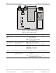
BAL
BNC
LOC
AMI
HDB3
DTE
JP11
JP9
ANA LOOP
BAL
BNC
JP6
JP1
JP2
JP3
JP4
TX & RX CODE
INT
EXT
RCV
J4
Figure 2-1. RIC-E1 Jumper Locations
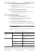
Table 2-1. RIC-E1 Jumper Settings
Jumper Description Values Default Setting
JP1, JP2, JP3, JP4,
JP6
Select the E1 interface type BAL – Balanced interface
(RJ-45 connector)
BNC – Unbalanced interface (BNC
coax connectors)
BAL
TX & RX CODE,
JP9
Selects the transmit and
receive coding
AMI – Jumper plug is installed
HDB3 – Jumper plug is not installed
HDB3
TIMING, J4 Selects the clock reference RCV (pin 4) – Receive clock
EXT (pin 5) – External clock
INT (pin 6) – Internal clock
RCV
Note: Units with the IR-ETH, IR-ETH/V and IR-IP interface modules support only receive and internal clocks.
ANA LOOP, JP11 Controls the local analog
loopback activation
LOC – Activates the local analog
loopback
DTE – Allows the activation of the
local analog loopback via DTE
DTE
Order from: Cutter Networks
Ph:727-398-5252/Fax:727-397-9610
www.bestdatasource.com