
- RAD Data Communications Modem User's Manual

ASMi-450 Control from the Control Port
ASMi-450 Installation and Operation Manual 4-21
on the remote unit.
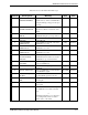
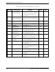
REMOTE UNIT Displays the state of the loopback that can be
INITIATED LOOPS activated by command from the remote
ASMi-450 unit on the local unit (this is REM
PORT, remote port loopback on the local unit,
toward the remote unit).
DSP ST SYS----------------------------------------------------------------------------------
Pur
p
ose
Display system status information.
Format
DSP ST SYS [option]
Use
To view the current system status, type:
DSP ST SYS<CR>
Dis
p
la
y
Format
A typical status information display is shown below.
NODE = 0
NAME = 'ASMi-450 name'
NODAL CLOCK = EXT
ASMI TYPE = CNTR
NUM OF ACTIVE TS = 24
SOFTWARE REV = X.Y
HARDWARE REV = X.Y
The system status fields are described below (from top to bottom)
NODE Displays the node number of the ASMi-450
NAME Displays the node name of the ASMi-450
NODAL CLOCK Indicates the current source for the ASMi-450 system clock:
INT or EXT (see Section 3-4).
NUM OF ACTIVE TS Indicates the number of active time slots configured on the
ASMi-450 (see Section 3-4).
ASMI TYPE Indicates the function of the ASMi-450: central or remote.
SOFTWARE REV Displays the ASMi-450 software version
HARDWARE REV Displays the ASMi-450 hardware version
EXIT---------------------------------------------------------------------------------------------
Pur
p
ose
End the current session and return control to the ASMi-450 front panel.
Format
EXIT
Use
Type:
EXIT<CR>