
- RAD Data Communications Modem User's Manual

Front-Panel Operating Instructions
ASMi-450 Installation and Operation Manual 3-3
Ethernet Interface
Indicators
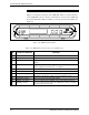
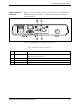
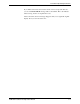
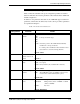
Figure 3-2 shows the indicators located on the rear panel of an ASMi-450 unit
with Ethernet interface, and Table 3-2 explains the functions of the Ethernet
interface indicators.
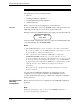
Figure 3-B. ASMi-450 Rear Panel (Ethernet Interface)
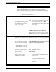
Table 3-B. Ethernet Interface Indicators
No. Indicator Function
1 LINK indicator Lights when the Ethernet interface is connected to an active LAN (i.e., a LAN
with at least one active station)
2 RX indicator Lights when receive activity is present on the Ethernet interface
3 TX indicator Lights when transmit activity is present on the Ethernet interface
4 COLL indicator Lights momentarily for each collision
1 2
4 3