
- RAD Data Communications Modem User's Manual

Connector Wiring
ASMi-450 Installation and Operation Manual A-5
A.4 HDSL Line Connector
The HDSL line is terminated in an eight-pin RJ-45 connector, designated LINE,
and wired in accordance with Table A-5.
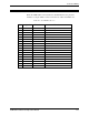
Table A-5. LINE Connector, Pin Allocation
Pin Function
1
2
3 through 8 Not Connected
A.5 RS-232 (V.24) Control Port Connector
The ASMi-450 control port has a standard RS-232 interface. The physical
interface is a 9-pin female connector, designated CONTROL DCE, wired in
accordance with Table A-6.
Table A-6 also lists the connections to the RS-232 interface of a control
terminal, and the connection to a modem (the terminal and the modem are
assumed to have 25-pin connectors).
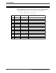
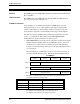
Table A-6. Control Port Interface Signals
Pin Line Notes
Connected
to Terminal
Connected to
Dial-Out Modem
1 Data Carrier Detect (DCD) From ASMi-450 8 4
2 Receive Data (RD) From ASMi-450 3 2
3 Transmit Data (TD) To ASMi-450 2 3
4 Data Terminal Ready (DTR) To ASMi-450 20 6
5 Signal Ground (SIG) Common reference and DC
power supply ground
7 7
6 Data Set Ready (DSR) From ASMi-450 6 20
7 Request to Send (Request to
Send (RTS))
To ASMi-450 4 8
8 Clear to Send (CTS) From ASMi-450 5 -
9 Ring Indicator (RI) To ASMi-450 - 22
Line