
- RAD Data Communications Modem User's Manual

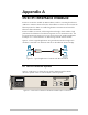

Appendix A IR-ETH Interface Module ASM-60 Installation and Operation Manual
A-4 Installation and Operation
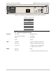
DIP Switch Settings
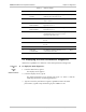
Table A-2 describes functions and default settings of the DIP switch SW-1 sections.
Table A-2. DIP Switch Settings
Section
Number
Name Description Default
Setting
1 SQ/FD ON – Full-duplex operation
OFF – Half-duplex operation
OFF
2 CMP ON – Strips padding bits inserted in 64-byte frame
OFF – Transmits frames over WAN as is
OFF
3 FIL ON – Passes only frames destined for another LAN
OFF – Disables LAN filter; passes all frames transparently
OFF
4
(nc)
LED Indicators
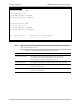
Table A-3 lists the IR-ETH LED indicators and describes their functions.
Table A-3. IR-ETH Bridge LED Indicators
LED
Name
Description Location Color
LINK ON indicates good link integrity Rear panel Green
COLL ON indicates collision on the attached Ethernet
segment
Rear panel Yellow
RX ON when data is received from the Ethernet
attached segment
Rear panel Yellow
TX ON when data is transmitted from the modem
to the Ethernet segment
Rear panel Yellow
ERR D4 Bridge buffer overrun On the
IR-ETH board
Red
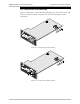
Connecting to LAN
When connecting an IR-ETH interface module with the UTP option, use either a
straight cable or a cross cable for the LAN connection. Use a cross cable when
connecting to a port that does not implement the crossover function internally.
Otherwise, use a straight cable.
Hubs usually do implement the crossover function internally, while network
interface cards and other devices do not.
Note