ASM-60 10 Mbps VDSL-Based Modem Installation and Operation Manual Notice This manual contains information that is proprietary to RAD Data Communications. No part of this publication may be reproduced in any form whatsoever without prior written approval by RAD Data Communications. No representation or warranties for fitness for any purpose other than what is specifically mentioned in this manual is made either by RAD Data Communications or its agents.
Warranty This RAD product is warranted against defects in material and workmanship for a period of one year from date of shipment. During the warranty period, RAD will, at its option, either repair or replace products which prove to be defective. For warranty service or repair, this product must be returned to a service facility designated by RAD. Buyer shall prepay shipping charges to RAD and RAD shall pay shipping charges to return the product to Buyer.
Safety Warnings The exclamation point within a triangle is intended to warn the operator or service personnel of operation and maintenance factors relating to the product and its operating environment which could pose a safety hazard. Always observe standard safety precautions during installation, operation and maintenance of this product. Only a qualified and authorized service personnel should carry out adjustment, maintenance or repairs to this instrument.
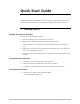
Quick Start Guide Installation of ASM-60 should be carried out only by an experienced technician. If you are familiar with ASM-60, use this guide to prepare the units for operation. 1. Installing ASM-60 Setting the Internal Switches Perform the internal settings as follows: 1. Disconnect the power cord from the power source. 2. Slide the blue side panel forward to detach it from the case. 3. Unscrew the two screws located on the bottom panel at the rear end of the unit. 4.
ASM-60 Installation and Operation Manual Quick Start Guide 2. Operating ASM-60 Normal Indications The table below shows the correct status of the indicators a few seconds after power-up. 3. Indicator Status PWR ON TD Depends on DTE data transmission. RD Depends on DTE data transmission. RTS Depends on DTE RTS signal status. DCD Depends on remote modem data transmission. TEST OFF ALM OFF SYNC A/SYNC B Green or red, depending on remote modem data transmission.
Contents Chapter 1. Introduction 1.1 Overview .......................................................................................................... 1-1 General ...................................................................................................................1-1 Versions...................................................................................................................1-1 Application ........................................................................................
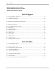
Table of Contents Appendix A. IR-ETH Interface Module Appendix B. IR-ETH/QH Interface Module Appendix C. IR-IP Interface Module List of Figures 1-1. Typical ASM-60 Application ...................................................................................... 1-1 1-2. 3D View of ASM-60 .................................................................................................. 1-3 1-3. ASM-60 Block Diagram ...........................................................................................
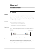
Chapter 1 Introduction 1.1 Overview General ASM-60 is a VDSL (Very High-bitrate Digital Subscriber Line) modem handling high data rates. ASM-60 supports HSSI DTE interface, and several Ethernet interface modules, which allow LAN-to-LAN connectivity using VDSL technology. Working in full duplex over 4-wire link, the modem can be configured to operate at the data rates up to 10.240 Mbps.
ASM-60 Installation and Operation Manual Chapter 1 Introduction Table 1-1. Typical ASM-60 Ranges Data Rate 24 AWG (Mbps) km miles 4.096 2.0 1.2 6.144 2.0 1.2 10.24 1.8 1.1 DTE Interface The ASM-60 DTE interface supports the following interfaces: • HSSI • IR-ETH module with built-in Ethernet bridge • IR-ETH/QH module with built-in Fast Ethernet bridge and VLAN support • IR-IP module with built-in IP router.
ASM-60 Installation and Operation Manual Chapter 1 Introduction 1.2 Physical Description Figure 1-2 shows a 3D view of the ASM-60 standalone modem. Figure 1-2. 3D View of ASM-60 The front panel includes nine LEDs, which display the status of power, data flow, control signals and provide diagnostics. The front panel also features a 9-pin D-type (CONTROL DCE) connector for terminal connection for configuration, control and monitoring. For detailed description of the front panel, see Chapter 3.
ASM-60 Installation and Operation Manual Chapter 1 Introduction 1.3 Functional Description This section provides a functional description (Figure 1-3) of ASM-60 in the form of block diagrams. TxD, RxD A11-A15 CPU INT, EXT Clock DTE Interface RS-232 Data, Clock Additional Decoder A0-A7, A14 D8-D15 EVM1 VDSL Framer HYBRID1 TRANSF.1 VDSL Line Interface Data, Clock EVM2 HYBRID2 Line A Line B TRANSF.2 Latch/Buffer 3.3V 5.0V LEDs AC Power Supply Control Figure 1-3.
ASM-60 Installation and Operation Manual Chapter 1 Introduction 1.4 Technical Specifications Line Interface Protocol Very High-bit-rate Digital Subscriber Line (VDSL) Type 4-wire, unconditioned dedicated lines (twisted pair), Cat.3 and Cat.5, 19 AWG to 26 AWG Line Coding QAM Range See Table 1-1 Levels 11 dBm Impedance 110Ω Return Loss More than 15 dB Carrier Constantly On DTE Interface Data Rate Type User-selectable: 4.096 Mbps, 6.144 Mbps or 10.
ASM-60 Installation and Operation Manual Chapter 1 Introduction Indicators Physical PWR (green) Power RTS (yellow) Request to Send TD (yellow) Transmit Data RD (yellow) Receive Data DCD (yellow) Data Carrier Detect TST (red) Test ALM (red) Alarm SYNC A (green/red) Synchronization line A SYNC B (green/red) Synchronization line B Height Width 215 mm / 8.5 in Depth 243 mm / 9.6 in Weight Power 1 kg / 3.
Chapter 2 Installation and Setup This chapter describes installation and setup procedures for the standalone ASM-60 modem. ASM-60 is delivered completely assembled. It is designed for tabletop or 19-inch rack installation. After installing the unit: • Refer to Chapter 3 for the operating instructions. • Refer to Chapter 4 for the detailed system configuration procedures using ASCII terminal connected to the ASM-60 control port.
Chapter 2 Installation and Setup ASM-60 Installation and Operation Manual 2.2 Package Contents The ASM-60 package includes the following items: • One ASM-60 unit • ASM-60 Installation and Operation Manual • AC power cord. 2.3 Installation and Setup The ASM-60 standalone unit is designed for desktop or bench installation and is delivered as a fully assembled unit. No provisions are made for bolting the unit to a tabletop. ➤ To install ASM-60: 1.
ASM-60 Installation and Operation Manual Chapter 2 Installation and Setup Opening the ASM-60 Case ➤ To open the ASM-60 case: 1. Disconnect the power cord from the power source. 2. Slide the blue side panel forward to detach it from the case. 3. Unscrew the two screws located on the bottom panel at the rear end of the unit. 4. Separate the two halves of the ASM-60 case by lifting the top cover at the end of the unit and sliding it forward.
ASM-60 Installation and Operation Manual Chapter 2 Installation and Setup Connecting the DTE The ASM-60 DTE interface provides interface for input/output data, clock reference and control signals between the modem and the DTE. The ASM-60 DTE interface can be either HSSI interface module, terminating in SCSI 50 female connector (see Table 2-2), or one of the Ethernet interface modules, described in greater detail in Appendix A, Appendix B and Appendix C.
ASM-60 Installation and Operation Manual Chapter 2 Installation and Setup Connecting the Power Warning Before switching on this unit and connecting any other cable, the protective earth terminals of this unit must be connected to the protective ground conductor of the power cord. If you are using an extension cord (power cable) make sure it is grounded as well.
Chapter 2 Installation and Setup 2-6 Installation and Setup ASM-60 Installation and Operation Manual
Chapter 3 Operation This chapter provides the description of the ASM-60 front-panel indicators, and details the modem's operating procedures (turn-on, front-panel indications, performance monitoring and turn-off). Installation procedures given in Chapter 2 must be completed and checked before attempting to operate ASM-60. 3.1 Front Panel Indicators The front panel of ASM-60 includes nine LED indicators that show the current operating status of the unit.
ASM-60 Installation and Operation Manual Chapter 3 Operation Table 3-1. ASM-60 LED Indicators (Cont.) Name Function SYNC A (red/green) ON (red) – Data link A is not synchronized with the remote modem. ON (green) – Data link A is synchronized with the remote modem. SYNC B (red/green) ON (red) – Data link B is not synchronized with the remote modem. ON (green) – Data link B is synchronized with the remote modem. 3.
Chapter 4 Management from a Terminal The configuration of ASM-60 is performed via menu-driven embedded software using a standard ASCII terminal or a PC running a terminal emulation application connected to the front panel CONTROL DCE port. This terminal can be used for performing the following management activities supported by ASM-60: • Modifying setup configuration • Monitoring of device status and settings • Collect performance statistics • Restarting ASM-60. 4.
ASM-60 Installation and Operation Manual Chapter 4 Management from a Terminal Table 4-1. Control Port Control Signals Control Line Interface Type DCE DTE CTS Out Not Used DCD Out Out DSR Out Out DTR In In RI Not Used In RTS In In Data Terminal Ready (DTR) When connected and turned on, the terminal sets the DTR line ON (active) to gain control over ASM-60 and starts a configuration or monitoring session. Initiating a Control Session ➤ To initiate a control session: 1.
ASM-60 Installation and Operation Manual Chapter 4 Management from a Terminal Terminal Management Menus Figure 4-1 shows a map of the management menus in the ASM-60 embedded software. The second level menus (Configuration, Display, Reset) are described in its own section in this chapter. The Alarms, Log File, VDSL Performance and Test menus are described in Chapter 5. Main Menu 1. Configuration 1. Data Rate 1. 4096 kbps 2. 6144 kbps 3. 10240 kbps 2. Display 1. Status 3. Test 4. Reset 1.
ASM-60 Installation and Operation Manual Chapter 4 Management from a Terminal ASM-60/CO Main Menu 1. Configuration 2. Display 3. Test 4. Reset 5. Debug > ESC - previous menu ; ! - main menu ; & - exit terminal ------------------------------------------------------- Figure 4-2. Main Menu Note At the bottom of the terminal screen, ASM-60 displays the latest alarms as they enter the alarm log. 4.4 Configuring ASM-60 This section describes the configuration procedures for the ASM-60 modem.
ASM-60 Installation and Operation Manual Chapter 4 Management from a Terminal Data Rate (current value) Enter the Devise Bit Rate 1. 4096 kbps 2. 6144 kbps 3. 10240 kbps > ESC - previous menu ; ! - main menu ; & - exit terminal ------------------------------------------------------- Figure 4-4. Data Rate Menu 4.5 Displaying the ASM-60 System Information The ASM-60 software allows to display the modem system information. ➤ To access the Display menu: • From the Main menu, type 2.
ASM-60 Installation and Operation Manual Chapter 4 Management from a Terminal Displaying the ASM-60 Status Main Menu ↓2 Display ↓1 Status You can display the current status of the local and remote ASM-60 modems. ➤ To display the ASM-60 status: • From the Display menu, type 1. The Status screen is displayed (see Figure 4-6). Status Device Rate: 6144 kbps Remote Status: ASM60/SA CO Active Software Version: 01.00 Hardware Version (PCB): 00 AFE Version: 00.
ASM-60 Installation and Operation Manual Chapter 4 Management from a Terminal 4.6 Resetting ASM-60 You can perform reset of the main components of ASM-60, or reset the modem to its factory settings. ➤ To reset ASM-60: 1. From the Main menu, type 4. The Reset menu appears (Figure 4-7). 2. From the Reset menu, choose one of the following: 1 – To reset ASM-60 to the default data rate – 10.240 kbps. 2 – To reset the ASM-60 CPU (if the Watchdog jumper on the V-Agent board is set to ON).
Chapter 4 Management from a Terminal 4-8 Resetting ASM-60 ASM-60 Installation and Operation Manual
Chapter 5 Diagnostics This chapter describes the ASM-60 diagnostic functions, which include: • Status indications, alarms, power-up self-test • VDSL performance diagnostics • LED testing. 5.1 Error Detection This section explains how to detect and fix errors and other problematic conditions in ASM-60. Power-Up Self-Test ASM-60 performs a hardware self-test upon turn-on. The self-test sequence checks the critical circuit functions of the modem.
ASM-60 Installation and Operation Manual Chapter 5 Diagnostics Alarms DCD Failed > ESC - previous menu ; ! - main menu ; & - exit terminal ------------------------------------------------------- Figure 5-1. Alarms Screen The display of the Alarms screen includes only the name of the alarm. Once the event that caused the alarm is cleared, the ALM indicator turns off.
ASM-60 Installation and Operation Manual Chapter 5 Diagnostics Table 5-1.
ASM-60 Installation and Operation Manual Chapter 5 Diagnostics VDSL Performance Line A Lock Status: SYNC Line A Avg. Snr.: 34 Line A BER pre FEC: 0.000E+00 Line A BER after FEC: 0.000E+00 Line B Lock Status: SYNC Line B Avg. Snr.: 34 Line B BER pre FEC: 0.000E+00 Line B BER after FEC: 0.000E+00 > ESC - previous menu ; ! - main menu ; & - exit terminal ------------------------------------------------------- Figure 5-3.
ASM-60 Installation and Operation Manual Chapter 5 Diagnostics 5.3 Running the Diagnostic Tests Running the LEDs Test The ASM-60 modem can perform the front-panel indicators test to verify that the unit LEDs are functioning properly. Main Menu ↓3 Test ↓2 Start LEDs Test ➤ To run the LEDs test: 1. From the Main menu, type 3. The Test menu appears. 2. From the Test menu, type 2 to run the LEDs test on ASM-60. All the front-panel LED indicators light up for 3 seconds.
Chapter 5 Diagnostics 5-6 Running the Diagnostic Tests ASM-60 Installation and Operation Manual
Appendix A IR-ETH Interface Module IR-ETH is an interface module for RAD modems, used for converting the Ethernet (10BaseT or 10Base2) electrical levels to the modem TTL levels. It also converts the Ethernet protocol to HDLC to enable long-distance transmission and avoid the Ethernet collision limitation. IR-ETH includes an internal, self-learning Ethernet bridge, which enables a high performance link between two Ethernet segments at a low transmission rate.
ASM-60 Installation and Operation Manual CAUTION : FOR CONTINUED PROTECTION AGAINST RISK OF FIRE, REPLACE ONLY WITH SAME TYPE AND RATING OF FUSE. LINE 10BASE-2 RX 100-230 VAC 0.250A T 250V Appendix A IR-ETH Interface Module COLL A-1 2 TX 4 5-B Figure A-3. Rear Panel of ASM-60 with IR-ETH Module (BNC Connector) Table A-1. RJ-45 Pinout Pin Function 3 RCV (+) 6 RCV (-) 1 XMT (+) 2 XMT (-) – GND A.
ASM-60 Installation and Operation Manual Appendix A IR-ETH Interface Module A.3 Installation and Operation Figure A-4 and Figure A-5 show the Ethernet bridge layout, the locations of the DIP switches, and the rear panel components for the UTP and the BNC versions, respectively. Figure A-4. IR-ETH Layout (UTP Option) Figure A-5.
ASM-60 Installation and Operation Manual Appendix A IR-ETH Interface Module DIP Switch Settings Table A-2 describes functions and default settings of the DIP switch SW-1 sections. Table A-2.
Appendix B IR-ETH/QH Interface Module B.1 Introduction The IR-ETH/QH interface module includes a high performance self-learning Fast Ethernet bridge, which is connected to the LAN via a single 10BaseT or 100BaseT port, operating in full duplex and providing offer simple and cost-effective interconnection between 10/100BaseT LANs via VDSL links. The IR-ETH/QH interface module also supports IEEE 802.1/Q frames, enabling VLAN applications.
ASM-60 Installation and Operation Manual Appendix B IR-ETH/QH Interface Module Table B-1. RJ-45 Connector Pinout Pin Signal Function 1 RD (+) Receive Data (positive) 2 RD (-) Receive Data (negative) 3 TD (+) Transmit Data (positive) 6 TD (-) Transmit Data (negative) B.3 Technical Specifications Bridge LAN LAN Table 1,000 MAC addresses Aging 5 minute, automatic Filtering and Forwarding Rate 150,000 packets per second Buffer Size 170 frames Delay 1 frame Standard IEEE 802.
ASM-60 Installation and Operation Manual Appendix B IR-ETH/QH Interface Module B.4 Installation and Operation Figure B-3 shows location of the configuration DIP switch on the module’s board. 87 6 5 4 3 2 1 S1 ON Figure B-3. DIP Switch Location Setting the DIP Switch Configure the IR-ETH/QH module by setting the DIP switch in accordance with Table B-2. The DIP switch is located on the reverse side of the IR-ETH/QH module.
Appendix B IR-ETH/QH Interface Module ASM-60 Installation and Operation Manual LED Indicators Table B-3 lists the IR-ETH/QH rear-panel LED indicators and describes their functions. Table B-3.
Appendix C IR-IP Interface Module C.1 Introduction Overview IR-IP is a high-performance, miniature IP router based on RAD's unique IP router chip, the ChipRouter. IR-IP works by taking each Ethernet frame from the LAN and determining whether the IP packet is destined for the IP net on the Ethernet LAN. If not, IR-IP forwards the packet to the WAN (VDSL) link. IP packets received from the WAN link are automatically forwarded to the LAN if the IP net matches.
ASM-60 Installation and Operation Manual Appendix C IR-IP Interface Module Application Figure C-1 shows a typical application of the ASM-60 modem equipped with the IR-IP interface module. ASM-60 with IR-IP ASM-60 with HSSI Interface Router Figure C-1. Typical Application of ASM-60 with IR-IP C.
ASM-60 Installation and Operation Manual Appendix C IR-IP Interface Module IR-IP LEDs IR-IP contains three LEDs, which indicate the module activity. Table C-1 lists the LEDs functions. Table C-1. IR-IP LEDs Functions Name Type Function INT Green LED ON – LAN integrity is established. ACT Yellow LED Blinks – Transmit/receive activity is detected on the Ethernet link. ERR Red LED ON – Buffer overflow occurred (during normal operation).
Appendix C IR-IP Interface Module ASM-60 Installation and Operation Manual C.
ASM-60 Installation and Operation Manual Appendix C IR-IP Interface Module Default IP Communication Parameters The default IP communication parameters of the interface module are: • The default IP address of the IR-IP Ethernet port is 192.168.205.1, and the default IP subnet mask is 255.255.255.252. • The port will accept IP communication only from the IP address 192.168.205.2.
Appendix C IR-IP Interface Module ASM-60 Installation and Operation Manual Connecting the Telnet Host Before starting the management and configuration activities, it is necessary to establish IP communication between your Telnet host and the IR-IP interface module. For this purpose, it is necessary to provide a communication path. Because of the method used to assign an IP address to IR-IP Ethernet port, it is recommended to connect the Telnet host directly to the IP router 10BASE-T connector.
ASM-60 Installation and Operation Manual Appendix C IR-IP Interface Module The IP address is actually retrieved from the ARP frames sent during pinging to locate the ping destination, not from the ping frames. To ensure that the process is correctly performed, it is recommended to check the contents of the ARP table before starting the ping utility, to make sure that it does not contain the address to be assigned to the IP router LAN interface.
Appendix C IR-IP Interface Module ASM-60 Installation and Operation Manual After changing the destination IP address of the Telnet host, it is recommended to turn ASM-60 off for a few seconds and then back on, before continuing the configuration of the IP router in accordance with the Quick Setup Menu section below. At this time, in Step 2 the ERR indicator turns off after the 15-second interval.
ASM-60 Installation and Operation Manual Appendix C IR-IP Interface Module C.6 IR-IP Management Utility General Operating Procedures The IR-IP interface module is managed via a simple, menu-driven utility that uses a basic terminal user interface. A typical screen is shown in Figure C-4. As seen in Figure C-4, each screen has a header that identifies the device being configured and its logical name, assigned by the user, followed by the running software revision and date.
ASM-60 Installation and Operation Manual Appendix C IR-IP Interface Module To end the utility, press when the Main menu is displayed. This will also end the Telnet session. Menu Structure of Management Utility Figure C-5 shows the menu structure of the IR-IP management utility. Main Menu 1. Quick Setup 2. Management Access 3. Advanced Setup 1.Telenet Password 2. Telenet Activity Timeout 3. SNMP Access 4. SNMP Read Community 5. SNMP Write Community 6. SNMP Trap Community 7.
ASM-60 Installation and Operation Manual Appendix C IR-IP Interface Module IR_IP S/W Ver. 1.00 31/IR (date) Quick Setup ===================================================================== 1. LAN IP Address :192.168.100.001 2. LAN IP Mask :255.255.255.000 3. WAN IP Address (empty for unnumbered) :............... 4. WAN IP Mask (empty for unnumbered) :............... 5. Default Gateway (empty - WAN interface) :............... 6. Read Protocol From DIP Switches :[ Yes ] 7.
Appendix C IR-IP Interface Module ASM-60 Installation and Operation Manual Default Gateway Operation without Default Gateway The IP interface module is intended to enable the extension of LANs through the ASM-60 VDSL link.
ASM-60 Installation and Operation Manual ➤ Appendix C IR-IP Interface Module To access the Management Access menu: • From the Main menu, type 2. The Management Access menu appears (Figure C-8). IR_IP S/W Ver. 1.00 31/IR (date) Quick Setup Management Access ===================================================================== 1. Telnet Password :.......... 2. Telnet Inactivity Timeout (min) :300.. 3. SNMP Access :Disabled 4. SNMP Read Community :public.... 5. SNMP Write Community :public....
ASM-60 Installation and Operation Manual Appendix C IR-IP Interface Module ➤ To access the Advanced Setup menu: • From the Main menu, press 3. The Advanced Setup menu appears (Figure C-9). IR_IP S/W Ver. 1.00 31/IR (date) Quick Setup Management Access Advanced Setup ===================================================================== 1. Device identification 2. Interface Parameters 3. Protocol Parameters 4. Multicast IP Press one of the numbers to select or ESC: Figure C-9.
ASM-60 Installation and Operation Manual Appendix C IR-IP Interface Module Contact Person Select this parameter to enter the name of the person to be contacted with matters pertaining to this equipment unit. System Location Select this parameter to enter the physical location of the device. Interface Parameters Menu The Interface Parameters menu is used to control the operation of IR-IP interfaces. ➤ To access the Interface Parameters menu: • From the Advanced Setup menu, type 2.
Appendix C IR-IP Interface Module ASM-60 Installation and Operation Manual The available selections are: • 64 kbps • 128 kbps • 256 kbps • 512 kbps • 1024 kbps • Full (no restriction on the rate). Since the IP router buffers have a limited capacity (256 frames), it is recommended to select the WAN Throttle parameter in accordance with the line rate. Aging Timeout Used to specify the time after which inactive LAN stations are removed from the IR-IP ARP table.
ASM-60 Installation and Operation Manual Appendix C IR-IP Interface Module EIR Used to specify the maximum amount of data, in bits, that the Frame Relay network will attempt to deliver during the measurement interval. The value of this parameter is obtained from the Frame Relay service provider. A typical Frame Relay Protocol Parameters menu is shown in Figure C-12. IR_IP S/W Ver. 1.00 31/IR (date) Quick Setup Management Access Advanced Setup ....................................................
ASM-60 Installation and Operation Manual Appendix C IR-IP Interface Module Security Host/Guest This option can be used to configure the IP router either as a guest unit, to be authenticated by another router, or as a host unit, that authenticates other routers. User Name To Send The name by which an IP router card configured as guest identifies itself. Password To Send The password by which an IP router card configured as guest identifies itself.
ASM-60 Installation and Operation Manual Appendix C IR-IP Interface Module Multicast IP Menu The Multicast IP menu is used to specify the IP multicast frame forwarding parameters, and to access the static multicast groups’ table. ➤ To access the Multicast IP menu: • From the Advanced Setup menu, press 4. The Multicast IP menu appears (Figure C-14). IR_IP S/W Ver. 1.00 31/IR (date) Quick Setup Management Access Advanced Setup ...................................................................
ASM-60 Installation and Operation Manual Appendix C IR-IP Interface Module Static Groups Select this parameter to access the static multicast groups table. The table is used to specify the IP addresses for up to 10 IP multicast groups. You can add, change, or delete each entry in the table (see the prompt line). ➤ To access the Static Groups menu: • From the Multicast IP menu, type 2. The following screen appears: IR_IP S/W Ver. 1.
ASM-60 Installation and Operation Manual Appendix C IR-IP Interface Module New Software Download Menu IR-IP operates as a TFTP client, and therefore it is possible to update its software by downloading new software from another computer that operates as a TFTP server. The New Software Download menu is used to specify the software downloading parameters. ➤ To access the New Software Download menu: • From the Device Control submenu, type 1. New Software Download menu appears (Figure C-17).
ASM-60 Installation and Operation Manual Appendix C IR-IP Interface Module View Error Log Screen This item of the Device Control submenu is used to view the error log file. This file logs errors detected in IR-IP for debug and technical support purposes. Resets Menu The Resets menu allows you to perform reset of IR-IP, or its interfaces. This operation can be used to restore normal operation after service is disrupted by an abnormal condition.
ASM-60 Installation and Operation Manual Appendix C IR-IP Interface Module Reset WAN ➤ To reset the WAN interface: • From the Resets menu, type 3. You will be prompted to confirm the reset operation. Note Resetting the WAN interface causes the WAN controller to be restarted. This results in renegotiation of the WAN protocol parameters. To continue your Telnet session, press any key within 15 seconds following the confirmation of the reset operation. C.
ASM-60 Installation and Operation Manual Appendix C IR-IP Interface Module IR_IP S/W Ver. 1.00 31/IR (date) BOOT Version Device Name System Location Contact Person VIEW CONFIGURATION -----------------:1.06 18.03.1999 :IP router card :The location of this device :Name of contact Person MAC Address Default Gateway : 00-20-D2-16-3F-9B : WAN Intrf Type Baud(Kbps) Prot IP Address IP Mask Status ..................................................................... LAN UTP ------Ethr 192.168.205.
ASM-60 Installation and Operation Manual IR_IP Appendix C IR-IP Interface Module S/W Ver. 1.00 31/IR (date) Multicast Groups Table ---------------------Group IP Address Status Group IP Address Status Press any key for exit Figure C-22. Multicast Groups Table Screen Statistics Screen The Statistics screen is used to display statistical information on the traffic between the networks connected by IR-IP. The data displayed on this screen enables you to evaluate the IR-IP performance.
ASM-60 Installation and Operation Manual Appendix C IR-IP Interface Module IR_IP WAN WAN WAN WAN WAN WAN WAN WAN WAN Counter Name in Octets Out Octets Out Frames to LAN Frames Transfer IP Datagram Received to CPU Discarded to LAN Discarded Out Errors CRC Errors S/W Ver. 1.
ASM-60 Installation and Operation Manual Appendix C IR-IP Interface Module Using the Ping Function The Ping option is used to confirm IP connectivity by pinging other IP hosts. Connectivity is confirmed by receiving a reply from the remote (pinged) IP host. ➤ To ping a host: 1. From the Diagnostic Tools menu, type 1 and enter the desired host IP address. 2. Press to confirm the destination IP address. 3. To start pinging, type 2 on the Diagnostic Tools screen.
Appendix C IR-IP Interface Module C.13 ASM-60 Installation and Operation Manual Erasing User’s Configuration The user-defined configuration parameters are stored in the IP router card flash memory. After the user-defined configuration parameters are erased, the IP router card automatically loads the default parameters. You may want to erase the current configuration parameters: 1. Before IR-IP is prepared for operation in a new application. 2.
ASM-60 Installation and Operation Manual Appendix C IR-IP Interface Module 2. Set all the four sections of IR-IP DIP switch to ON. 3. Turn the ASM-60 on and monitor the IP router ERR indicator: it must turn on and light steadily. Note 4. While the ERR indicator is lit (within 15 seconds), set sections 3 and 4 of IR-IP DIP switch to OFF. The IP router application software is erased.
Appendix C IR-IP Interface Module C-30 Erasing IR-IP Software ASM-60 Installation and Operation Manual