
- RAD Data Communications Network Card User's Manual
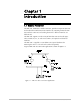

Chapter 2. Installation
ARC-101
Installation & Operation Manual
2-4 Cable Connections
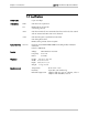
When the ARC-101 is used as a DCE or as a DTE, the RJ-45 pinout is:
Pinout DCE DTE
Pin 1
Pin 2
Pin 3 DTR
Pin 4 GND GND
Pin 5 TX Data RX Data
Pin 6 RX Data TX Data
Pin 7 CTS
Pin 8
Pin 9 RTS
Changing
Control Port Mode
The ARC-101 is shipped as a DCE. To connect the ARC-101 to a MODEM,
the control port mode must be configured to DTE.
To change the control port mode from DCE to DTE, or vice versa:
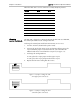
1. Turn the unit OFF (disconnect the power cord).
2. Unscrew the twelve box cover screws and remove the box cover. The
12 pin DCE/DTE jumper is located on the left side of the ARC-101
mother board when viewed from the rear panel (see Figure 3-2).
3. To change the configuration to:
•
DTE, place the 12 pin jumper on the upper 12 pins.
•
DCE, place the 12 pin jumper on the lower 12 pins.
4. Replace the box cover and tighten the screws.
Figure 2-4 Jumper Settings for DTE
(Two upper pins connected)
Figure 2-5 Jumper Settings for DCE
(Two lower pins connected)