VBOX II User Guide VBOX II 20Hz GPS Data Logger User Guide Page 1 of 23
VBOX II User Guide VBOX II OVERVIEW........................................................................................................................................................................... 3 INTRODUCTION................................................................................................................................................................................. 4 FEATURES .....................................................................................................
VBOX II User Guide VBOX II Overview Page 3 of 23
VBOX II User Guide Introduction nd The VBOX II represents the 2 generation of GPS data logging system from Racelogic. Using a powerful GPS engine, the VBOX II can log GPS and other data at 20Hz. The logged data is stored directly onto a compact flash card for easy transfer to a PC. The VBOX II is compatible with all of the existing peripherals including the Multifunction display, ADC03, TC8, FIM02 and Yaw rate sensor.
VBOX II User Guide Standard Inventory Description VBOX II Battery Pack with built in 12 Volt Charger Mains Charger Cigar Lighter adaptor GPS Magnetic Aerial 32Mb Compact Flash Card PCMCIA Compact Flash Adaptor CD ROM containing VBOX software Serial PC Cable User Manual Padded Carrying Case Qty 1 1 1 1 1 1 1 1 1 1 1 Racelogic Part # VB2DCF RLVBACS012 RLVBACS020 RLVBCAB10 RLVBACS001 RLVBACS005 RLVBACS028 RLVBACS030 RLVBCAB01 RLVBACS031 RLVBACS013 Optional Accessories Description Brake Pedal Trigger Hand-h
VBOX II User Guide Operation Power The VBOX II can be powered from a wide range of voltage sources including the Vehicle Cigar adapter, the supplied Ni-Mh battery pack or other source provided by the user. The maximum operating voltage input must not exceed 18V DC. Failure to observe this could result in damage to the VBOX. The battery pack is a 6v 3.8amp hour Nickel Metal Hydride unit, with a built in charging and monitoring circuit.
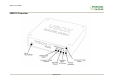
VBOX II User Guide LED indicators The green LED (ST) is used to indicate the number of satellites currently in lock. If the yellow LED (SC) is flashing whilst the green (ST) LED is off, then the VBOX has no satellite lock. If this is the case then check that you have the GPS antenna connector correctly fitted to the VBOX. Also check that the antenna has a clear view of the sky. The VBOX will normally lock onto satellites within 30 seconds of power up.
VBOX II User Guide Memory Cards The VBOX II can accept Type-I compact flash memory cards. The memory cards must be formatted using FAT or FAT16 but not FAT32. This option is normally selectable when formatting the memory card in a card reader connected to a PC. When logging data to compact flash the blue CF LED will flash or be constantly illuminated. It is important not to remove the flash card while the blue LED is illuminated.
VBOX II User Guide DIGITAL and ANALOGUE OUTPUTS The digital output on connector 6 is a frequency/pulse output corresponding to velocity. The pulse per meter range is adjustable in software. The analogue output on connector 4 outputs 0-5volt DC signal corresponding to velocity.
VBOX II User Guide Digital Inputs The DIGITAL IN/Socket3 contains the two digital inputs for the VBOX II. Digital input 1 is also referred to as the Brake trigger input. This input is connected to an internal timer capture module that is able to record precisely an event time for use in brake distance calculation. This period of time is called the trigger event time, and is logged as the value in milliseconds between the trigger event and the last GPS sample.
VBOX II User Guide CAN / RS232 Ports The VBOX II is equipped with a CAN Bus interface and a RS232 serial port. The RS232 port is used for all communication between the VBOX and laptop PC. The RS232 port is in Socket 5 on the VBOX II. The RS232 port is able to transmit live data from the VBOX to the PC for viewing and performing real-time tests. The CAN Bus port is in Socket 2 of the VBOX II.
VBOX II User Guide Getting Started Required equipment (All supplied as standard unless specified) VBOX II Fully charged battery pack or Cigar lighter 12v adapter lead GPS Antenna Blank Compact Flash Card RS232 Cable VBOX Software CD Laptop PC(not supplied) 1.Install Software 2.Place VBOX in vehicle 3.Fit antenna connector to VBOX 4. Mount GPS antenna on vehicle roof 5.Connect serial cable (CAB01) to laptop 6.
VBOX II User Guide 7. Connect the power cable/ battery pack to the VBOX 8. If using 12v power cable, connect to vehicle 9. With the power applied, the red PWR led should illuminate. The VBOX II will start searching for satellites. The ST led will indicate the number of satellites currently in lock. For best results ensure the VBOX has acquired a lock on 5 or more satellites, essential for quality signal reception.
VBOX II User Guide VBOX II ‘.VBO’ file format The VBOX II data files are saved in standard space de-limited text format. This allows the data to easily be imported into third party applications such as word processors or spreadsheets. The files each contain a header section before the main data that describes the channel content and information about the VBOXII such as serial number and firmware version. The [Column names] parameter specifies the data in each column of the data section.
VBOX II User Guide VBOX.EXE Software The VBOX.EXE software is used for configuration of the VBOX II and also for analysis of the VBO data files. For further information on the VBOX.EXE software refer to the VBOX Software manual supplied with VBOX II.
VBOX II User Guide Firmware Upgrades Firmware refers to the operating software inside the VBOX II. The firmware is responsible for all of the functions within the VBOX and from time to time, firmware updates will be released by Racelogic to improve or enhance the way that the VBOX works. The latest firmware will always be available on the Racelogic web site in the downloads directory:http://www.racelogic.co.uk/2003/vbox/downloads.htm It is recommended to check the web site periodically for updates.
VBOX II User Guide Specification GPS Velocity Accuracy Distance Accuracy 0.05% (<50cm per Km) Units Update rate Resolution Height accuracy Height accuracy with DGPS Metres / Feet 20Hz 1cm 6 Metres 95% CEP** 2 Metres 95% CEP** Time Resolution Accuracy 0.01 s 0.01 s Units Update rate Maximum velocity Minimum velocity Resolution 0.1 Km/h (averaged over 4 samples) Km/h or Mph 20 Hz 1000 Mph 0.1 Km/h 0.01 Km/h Absolute Positioning Accuracy Accuracy with DGPS Update rate Resolution 3m 95% CEP** 1.
VBOX II User Guide Outputs CAN Bus Bit rate Identifier type Data available Analogue Voltage range Default setting * Accuracy Update rate 250Kbits ,500Kbits & 1Mbit selectable baud rate Standard 11bit 2.0A Satellites in View, Latitude, Longitude, Velocity, Heading, Altitude, Vertical velocity, Distance, Longitudinal acceleration & lateral acceleration, Distance from trigger, Trigger time, trigger Velocity 0 to 5Volts DC Velocity 0.0125Volts per Km/h (0 to 400Km/h) 0.
VBOX II User Guide Connection Data 3 pin LEMO socket 2 pin LEMO socket Connector PIN 1 2 Chassis 1 POWER In/Out Description I Power + I Ground Ground Connector PIN 1 2 3 Chassis 3 DIG IN In/Out O I I Type Lemo 2 pin Type Lemo 3 pin Description Ground Digital Input 2. Start/Stop Logging Digital Input 1.
VBOX II User Guide Connector PIN 1 2 3 4 5 Chassis 2 CAN Bus Type Lemo 5 pin In/Out Description O RS232 Tx (PORT B Local DGPS) I RS232 Rx (PORT B Local DGPS) I/O CAN Bus I/O CAN Bus O +V Power Ground Connector PIN 1 2 3 Chassis 4 Analogue OUT Type In/Out Description O Analogue Voltage Output O Ground Ground Connector PIN 1 2 3 4 5 Chassis 5 RS232 In/Out O I O Connector PIN 1 2 3 Chassis 6 Digital OUT Type In/Out Description O Digital Pulse Output O Ground Ground Range ±12v ±12v Lemo 3 pin Range 0V
VBOX II User Guide Antenna connector Connector PIN Center Chassis ANT In/Out - Type SMA Description RF Signal / Power for active antenna Ground Range Page 21 of 23
VBOX II User Guide CAN Bus data format ID** Update rate 50ms Data Bytes 1 2 3 4 5 6 7 8 0x301 (1) Sats in (2) Time since midnight UTC (3) Position – Latitude DDMM.MMMMM view 0x302 50ms (4) Position – Longitude DDMMM.MMMMM (5) Velocity. (Knots) (6) Heading. (Degrees) 0x303 50ms (7) Altitude. WGS 84. (Metres) (8) Vertical velocity. (M/S) Unused (9) Status (10) Status 0x304 50ms (11) Distance. (Meters) (12) Longitudinal Accel. (G) (13) Lateral Accel.
VBOX II User Guide Contact Information Racelogic Ltd Unit 10 Swan Business Centre Osier Way Buckingham MK18 1TB UK Tel: +44 (0) 1280 823803 Fax: +44 (0) 1280 823595 Email: support@racelogic.co.uk Web: www.racelogic.co.