VBOX3i 100Hz GPS Data Logger User Guide
VB3i MANUAL This page intentionally left blank Page | 2 22 May 2014
VB3i MANUAL Contents EC declaration of conformity ...................................................................................................... 5 Introduction ............................................................................................................................... 5 Features ..................................................................................................................................... 5 Inputs/outputs .....................................................
VB3i MANUAL IMU integration ....................................................................................................................... 19 Required equipment ..................................................................................................................................................... 19 Setup .............................................................................................................................................................................
VB3i MANUAL EC declaration of conformity We declare that this product has been tested to and meet the requirements of: EC directive 2004/104/EC “Adapting to technical progress council directive 72/245/EEC relating to the radio interference (electromagnetic compatibility) of vehicles and amending directive 70/156/EEC on the approximation of the laws of the member states relating to the type-approval of motor vehicles and their trailers.
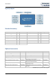
VB3i MANUAL Inputs/outputs Standard inventory Description Qty RL Part # VBOX3i data logger 1 RLVB3I-V2 Mains power supply 1 RLVBACS020 Cigar lighter power supply 1 GPS magnetic antenna Description Qty Racelogic Part # Serial PC cable 1 RLCAB001 25 Way D connector 1 ADC25IPCON RLCAB010L VBOX3i audio headset 1 RLACS120 1 RLACS158 VB3I Bluetooth antenna 1 RLACS119 4GB compact flash card 1 RLACS098 USB A – mini Lead 2m 1 RLCAB066-2 USB multi card reader 1 RLACS163 VBOX p
VB3i MANUAL Quickstart guide Required equipment (All supplied as standard unless specified) VBOX3i Cigar lighter 12v adapter lead GPS antenna Blank compact flash card RS232 cable VBOX software CD Laptop PC (not supplied) 1. Mount the VBOX3i GPS antenna in a suitable position on the roof of the vehicle. The ideal position is in the centre of the roof away from any objects that may shadow the GPS signal such as roof bars.
VB3i MANUAL Operation Power Included with the VBOX3i is a cigar lighter power cable, which is the primary source of power input. This is terminated in a 2-way connector and mates with the 2-way ‘PWR’ socket on the VBOX3i. The VBOX3i can be powered from a wide range of voltage sources, when considering batteries as a power source please note that the minimum operating voltage of the VBOX3i is 7V. The maximum operating voltage input must not exceed 30V DC.
VB3i MANUAL Logging The VBOX3i has three logging modes that are selected and configured via VBOX setup with the supplied VBOXTools software. Log continuously: With ‘log continuously’ ticked the VBOX will log data, regardless of movement. Log only when moving: Without ‘log continuously’ ticked then the VBOX will only log data to the CF card when it detects speed >0.5Km/h.
VB3i MANUAL DIFF/DGPS: Solid orange indicates a DGPS lock (either WAAS/EGNOS or 40cm local DGPS) Solid green indicates a 2cm ‘Fixed’ RTK lock PWR: Solid green indicates that a suitable power source is connected. Solid red indicates that the VBOX is not ready to operate either because it is still booting up or because there is an error condition. D IN: Solid green indicates that the brake trigger input has been activated/triggered.
VB3i MANUAL GPS antenna The GPS antenna supplied with the VBOX3i is a 5V active antenna. For the best possible signal quality, it is important to maintain a clean connection between the antenna and the VBOX3i. Before fixing the antenna to the VBOX3i, ensure that there are no dust particles in either connector. Replacement antennae are available by contacting your VBOX3i distributor. The antenna is a magnetic mounting type for quick and simple mounting to the vehicle roof.
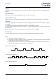
VB3i MANUAL Analogue and digital outputs (AD1 & AD2) The AD1 and AD2 connectors each have 1 analogue voltage and 1 digital output. The digital output on connector AD2 is a frequency/pulse output corresponding to velocity. The pulse per meter range is adjustable in software. The digital output on connector AD1 is a simple on/off state output. This digital output can be associated with any of the data channels being logged by the VBOX.
VB3i MANUAL Analogue inputs (A IN) The VBOX3i contains four differential 24bit analogue input channels with a maximum sample rate of 100Hz. Each channel has its own dedicated analogue to digital (A/D) converter with all four channels being sampled synchronously to each other. The voltage range of the input channels is ±50volts. Note that unlike the ADC03 module, the analogue channels in the VBOX3i are not electrically isolated from each other.
VB3i MANUAL RS232 serial / CAN VBOX3i is equipped with 2 CAN Bus interfaces and 2 RS232 serial ports. The primary RS232 port is used for all communication between the VBOX and laptop PC. The primary port is marked RS232 on the VBOX3i front panel. The primary RS232 port is able to transmit live data from the VBOX to the PC for viewing and performing real-time tests.
VB3i MANUAL VCI CAN input (vehicle CAN interface) The VBOX3i can log up to 16 user defined CAN bus signals on CAN port B. Configuration is performed using the VCI modules tab under log channels in VBOXTools software setup window. CAN signal parameters can be entered manually by the user or imported directly from a CAN database (.DBC) file if available.
VB3i MANUAL CANVEL If an input channel is given the name “CANVEL” then the VBOX3i will translate the data of this channel directly through to the GPS speed channel under the following criteria. IMU integration is not enabled The VBOX3i cannot calculate speed, i.e. no satellite signal (complete satellite drop out) The VBOX3i will scale the input channel to the default speed output format of Km/h according to what the units have been assigned to the substitution speed channel.
VB3i MANUAL Bluetooth The VBOX3i comes equipped with a Bluetooth radio allowing configuration of the VBOX remotely along with remote output of real-time VBOX3i serial data, at the full 100Hz data rate, to any Bluetooth capable PC or Data logger. Pairing your computer with the VBOX3i The VBOX3i will need the Bluetooth antenna connected and the computer will require a Bluetooth module or dongle to establish a virtual connection.
VB3i MANUAL VBOXTools software The VBOXTools software is used for configuration of the VBOX3i and also for analysis of the VBO data files. For further information on the VBOXTools software refer to the VBOXTools user manual supplied with VBOX3i. Software installation The VBOX3i setup software must be installed onto the hard drive of a computer; it cannot be run from the installation CD. To install the software insert the CD into the CD drive of your computer. The default installation language is English.
VB3i MANUAL IMU integration Required equipment IMU04 VB3i-V3 IMU04 VBOX Tools RLCAB119 VBOX – IMU connecting cable RLCAB001 / RLCAB066-2 – VB3i PC connection cable File manager (optional) IMU03 VB3i (works with all VB3i units) IMU03 VBOX Tools RLCAB005-CS VBOX – IMU connecting cable RLCAB001 / RLCAB066-2 – VB3i PC connection cable File manager (optional) Setup Important note: IMU04 must be connected to VB3i before power is applied to ensure data is correctly synchronised. 1.
VB3i MANUAL Hardware Setup Initialisation When using IMU integration, an initialisation phase is required when the IMU is first connected to the VBOX after being set up. This will be run through automatically after the VBOX has successfully gained satellite lock. When the IMU LED on VB3i front panel has turned a flashing green, the initialisation is complete. Note, if you are using a VB3iV1, which has no IMU LED, read the LED indicators section below for LED behaviour.
VB3i MANUAL Kalman Filter calibration – High dynamic tests To produce the optimum level of accuracy as quickly as possible, a series of specific manoeuvres can be performed that help the Kalman filter characterise the outputs from the IMU. Note that while this is recommended, it is not completely necessary as the Kalman filter will have enough data to achieve accurate results within a few minutes of normal dynamic driving (including left and right hand turns, braking and accelerating).
VB3i MANUAL Additional IMU channels (IMU04 only) IMU Attitude When using IMU04 integration with a VB3i-V3, there are three IMU attitude channels which can be logged. These body angle channels are heading, pitch and roll calculated from IMU derived data. RMS Channels These four channels are for diagnostic purposes only and cannot be turned on or off. They show the noise which is present on the vertical and horizontal speed channels, as calculated by the VB3i GPS engine.
VB3i MANUAL Mounting the IMU The IMU should be mounted rigidly to the vehicle mid-way along the wheelbase. Try to position the unit as close as possible to the centre of the vehicle, making sure it is mounted in the direction of travel - as shown in the image above. It is also important to mount the sensor so that it is level with the ground.
VB3i MANUAL Troubleshooting Trouble locking onto satellites If the VBOX3i is having trouble locking onto satellites then please follow the checklist below for typical solutions: Ensure that the antenna is placed in a position where it has an unobstructed view of the sky. (See ‘GPS antenna placement’ below) Check the antenna connection with the VBOX3i; only small amounts of dirt in the socket can cause a significant reduction in signal strength.
VB3i MANUAL VBOX3i V3 specification GPS Velocity Accuracy Distance Accuracy 0.05% (<50cm per Km) Units Update rate Resolution Height accuracy Height accuracy with DGPS Metres / Feet 100Hz 1cm 6 Metres 95% CEP** 2 Metres 95% CEP** Brake Stop Accuracy Accuracy +/- 2cm Time Resolution Accuracy 0.01 s 0.01 s Units Update rate Maximum velocity Minimum velocity Resolution Latency 0.1 Km/h (averaged over 4 samples) Km/h or Mph 100 Hz 1000 Mph 0.1 Km/h 0.01 Km/h 6.
VB3i MANUAL Connection data Front View of VBOX3i V1 2 PIN LEMO socket Connector PIN 1 2 Connector PIN 1 2 3 1 POWER In/Out I I 2 AD 1 In/Out O O I Connector PIN 1 2 3 Connector PIN 1 2 3 Connector PIN 1 2 3 4 5 Connector PIN 1 2 3 4 5 Connector PIN Center Chassis 3 AD 2 In/Out O O I 4 D IN In/Out I I I 5 CAN In/Out O I I/O I/O O 6 SER In/Out O I I/O I/O O ANT In/Out - Page | 26 Front View of VBOX3i V2/V3 3 PIN LEMO socket Type 5 PIN LEMO socket Lemo 2 pin Description Power + Ground Range 7V to 3
VB3i MANUAL Analogue input connector V1/V2 View of Socket on VBOX 3i Connector: Analogue Type: Sub-D 25-way Socket PIN 1 In/Out I Description Channel 1 + 2 3 4 5 6 7 8 9 10 11 12 13 I I I I I I I Channel 1 Channel 2 + Channel 2 Channel 3 + Channel 3 Channel 4 + Channel 4 - Range Connector: Analogue PIN In/Out 14 O 15 16 17 18 19 20 21 22 23 24 25 O O O Type: Sub-D 25-way Socket Description Vbatt GND 5 V Out GND Range Equal to Input Voltage. 100mA 5V ±2%.
VB3i MANUAL CAN output The VBOX3i has a CAN output which is present on the 5-way connector output; Data format: Motorola; Baud rate: 500Kb/s. Format ID** Motorola Data Bytes 1 2 3 4 0x301 (1) Sats in view (2) Time since midnight UTC 0x302 (4) Position – Longitude MMMMM.MMMMM 0x303 (7) Altitude. WGS 84. (Metres) 5 6 7 8 (3) Position – Latitude MMMM.MMMMM (5) Velocity. (Knots) (8) Vertical velocity. (M/S) (6) Heading. (Degrees) Unused (9) Status (10) Status 0x304 (11) Distance.
VB3i MANUAL Upgrading VBOX3i firmware Occasionally Racelogic releases new versions of firmware (internal code) for VBOX3i products, often to introduce new features. New firmware is loaded into the VBOX3i using a computer and a CF card. The latest firmware upgrade file for the VBOX3i is available from the Racelogic website.