VBOX Micro User Guide Issue 1 06 August 2014
VBOX MICRO MANUAL This page is intentionally left blank Page | 2 06 August 2014
VBOX MICRO MANUAL Contents Introduction........................................................................................................................................... 4 What Can The VBOX Micro Do? .............................................................................................................. 5 Additional Features ................................................................................................................................ 5 VBOX Micro Inputs and Outputs ........
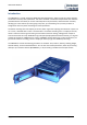
VBOX MICRO MANUAL Introduction The VBOX Micro is a small, waterproof (IP66) GPS data-logging device, which records your speed, position, acceleration and many other parameters. This data is stored on a removable compact flash card. Software provided with the unit allows you to view and analyse all of the parameters, which have been recorded, allowing you to see how fast you were going at any time, your maximum g-force, where you went on Google Earth and many other interesting and useful parameters.
VBOX MICRO MANUAL What Can The VBOX Micro Do? Measure speed, distance and acceleration Analyse driving line Compare driving style with others See if the most is being made of tyres during braking and cornering Plot routes on Google Earth Measure acceleration figures, top speed, ¼ mile etc. Take it anywhere – IP66 sealed against water, mud, dust etc.
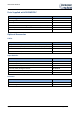
VBOX MICRO MANUAL Parts Supplied with RLVBMIC01C Description Product Code 10Hz Data logger VBMIC01C GPS Magnetic Antenna RLVBACS018 4GB Compact Flash Card RLACS098 Power Cable – 2W Fischer – Cigar Plug (VBOX MICRO power lead) RLCAB010F VBOX Carry Case RLACS106 USB A - USB Mini B – 2m RLCAB066-2 Optional Accessories Cables Description Product Code 5-way Fischer to 9 way ‘D’ connector (female) – 1m (CAN cable) RLCAB19F 9-way ‘D’ connector (male) to OBDII connector – 1.
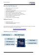
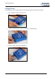
VBOX MICRO MANUAL Getting Started The VBOX Micro can be used to log data once the following simple steps have been followed. 1. Insert a suitable CF card and close the door. 2. Connect the GPS antenna; ensure it is mounted in a suitable position. 3. Connect a power supply to the VBOX Micro.
VBOX MICRO MANUAL Connecting Power To The VBOX Micro The VBOX Micro can be powered from two different types of power source, via the 2way PWR input socket. 1) Vehicle power outlet socket (via a supplied cigar lighter power cable RLCAB060) 2) Battery power, (Racelogic 2Ah Battery pack RLACS110) You must connect the GPS antenna before connecting power to the VBOX Micro.
VBOX MICRO MANUAL Logging Logging Control Logging of data to the CF card can be controlled in two ways: Opening the CF card door; this triggers a micro switch that stops the logging and closes the file. Closing the door will restart the logging to a new file. Pressing the ’■’’ button, this will stop the logging and close the current file. Pressing the ’■’’ button again will then re-start the logging to a new file.
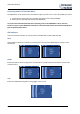
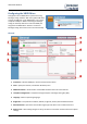
VBOX MICRO MANUAL Configuring the VBOX Micro Configuration of the VBOX Micro is performed using Racelogic Config software. With the supplied USB cable, connect the USB port on the VBOX Micro to one of the computers USB ports. When connecting to Racelogic config use the drop down list to select the COM port assigned to the VBOX Micro. Once this is selected Racelogic Config will connect to the unit automatically. General 1. Connection - Selected COM port, refresh and disconnect buttons. 2.
VBOX MICRO MANUAL Log settings To adjust the logging mode and the log rate of the VBOX Micro, open the ‘Logging’ tab in Racelogic Config. Once the logging mode and rate have been set, click the ‘Write Settings’ button to program the new configuration into the VBOX Micro. The log rate is shown as a frequency (in Hz) and also as a time period (in ms). Both options are linked so if one is altered the other setting will automatically reflect the change.
VBOX MICRO MANUAL Connecting an Input Module to the VBOX Micro The VBOX Micro can connect to any one of the following Racelogic input modules and then include the data from each channel in the logged VBO file. The VBOX Micro will automatically log all channels from a connected Input Module providing that the module is connected before the power is switched on.
VBOX MICRO MANUAL Configuring and using the VCI input (VBMIC01C only) The VBMIC01C version of the VBOX Micro has the ability for its CAN port to be used as a 16 channel vehicle CAN interface. NOTE: When the VBOX Micro is configured in VCI mode it is not possible to connect and log data from Racelogic input modules. Cables required Description Product Code 5-way Fischer to 9 way ‘D’ connector (female) – 1m (CAN cable) RLCAB019F 9-way ‘D’ connector (male) to OBDII connector – 1.
VBOX MICRO MANUAL Baud Rate The VCI CAN bus’ baud rate is configured by selecting the desired baud rate from the right hand side of the Racelogic Config CAN tab. Configuring a VCI channel To configure a VCI channel click on the channel box that needs to be setup, this will open a new configuration window. All CAN attributes for channel configuration can be manually configured from within this window, shown below.
VBOX MICRO MANUAL Loading a CAN database file Each of the 16 CAN channels can be configured from a CAN database file. From each channels setup window a CAN database file can be loaded by clicking the ‘Database’ button. Clicking the ‘Database’ button allows a CAN database file to be opened and then a signal from the Database can be selected. This will then automatically configure the channel with the correct CAN settings. DATA Base format types .VCI - Racelogic CAN database file .
VBOX MICRO MANUAL Satellite lock Antenna The GPS antenna supplied with the VBOX Micro is a 3.5V active antenna. For the best possible signal quality, it is important to maintain a clean connection between the antenna and the VBOX Micro. Before fixing the antenna to the VBOX Micro, ensure that there are no dust particles in either connector. Replacement antennae are available by contacting your VBOX Micro distributor. The antenna is a magnetic mounting type for quick and simple mounting to the vehicle roof.
VBOX MICRO MANUAL Upgrading the VBOX Micro’s Firmware Occasionally Racelogic releases new versions of firmware (internal code) for VBOX products, often to introduce new features. New firmware can be loaded into the VBOX Micro using a computer and the supplied USB cable. The latest firmware upgrade (.RUF) file for the VBOX Micro is available from the Racelogic website in the ‘Support’ section. http://www.velocitybox.co.
VBOX MICRO MANUAL Connectors Assignments 2 PIN LEMO socket 5 PIN LEMO socket POWER - 2 PIN LEMO socket PIN In/Out Description 1 I Power + 2 I Ground Range 6V to 30V 0V COMS – 5 PIN LEMO socket PIN In/Out Description 1 I/O Power 2 O RS232 Tx 3 I RS232 Rx 4 I/O CAN H 5 I/O CAN L ANTENNA - SMA connector PIN In/Out Description Centre RF Signal / Power for active antenna Chassis Ground Page | 18 06 August 2014
VBOX MICRO MANUAL Specification Velocity Accuracy Units Maximum update rate Maximum velocity/ Minimum velocity Resolution Latency 0.2 Km/h (averaged over 4 samples) Km/h or Mph 10 Hz 1000 Mph/0.1 Km/h 0.01 Km/h >160ms Distance Accuracy Units Maximum update rate Resolution 0.05% (<50cm per Km) Metres / Feet 10 Hz 1cm Absolute Positioning Accuracy Height accuracy Maximum update rate Resolution 5m 95% CEP** 10 Metres 95% CEP** 10 Hz 1 cm Heading Resolution Accuracy 0.01° 0.
VBOX MICRO MANUAL Module Dimensions Contact details Racelogic Unit 10 Swan Business Centre Osier Way Buckingham Bucks MK18 1TB United Kingdom Email: support@racelogic.co.uk Web: www.racelogic.co.