
Technical data


1260-43 User Manual Publication No. 980673-067 Rev. B
Module Operation 3-46 Astronics Test Systems
Matrix Load
Configuration
Each matrix has two loads that can be configured as a pull-up or
pull-
down. Each load has 5 relay pairs used to select the load
value and set it as a pull-up or pull-down. The two loads can be
used in conjunction to form a pull-up/pull-down load.
Once configured, each load can be tied to one of the ten buss
signals. This is accomplished using 10 relays, one for each buss
signal. Care should be taken that only one buss/load relay is
activated at any one time. This assures that buss signals are not
shorted together. Both loads can be tied to the same buss signal
to form a pull-up/pull-down load.
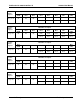
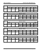
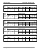
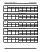
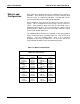
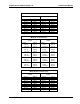
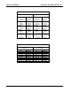
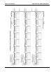
The following tables illustrate the activation of the corresponding
relays to form pull-up or pull-down loads for each of the three
matr
ices. For the following tables, Kxxx is the reference
designator of the relay used while the ‘1’ or ‘0’ is the state of the
relay activation bit written in the corresponding register.
Table 3-3, Matrix Load Selection
Matrix A “Load Selection”
Load 1 Load 2
50 Ohm
Pull-up
Pull-down
K186=1
K181=1
K181=0
50 Ohm
Pull-up
Pull-down
K196=1
K191=1
K191=0
75 Ohm
Pull-up
Pull-down
K187=1
K182=1
K182=0
75 Ohm
Pull-up
Pull-down
K197=1
K192=1
K192=0
100 Ohm
Pull-up
Pull-down
K188=1
K183=1
K183=0
100 Ohm
Pull-up
Pull-down
K198=1
K193=1
K193=0
500 Ohm
Pull-up
Pull-down
K189=1
K184=1
K184=0
500 Ohm
Pull-up
Pull-down
K199=1
K194=1
K194=0
1K Ohm
Pull-up
Pull-down
K190=1
K185=1
K185=0
1K Ohm
Pull-up
Pull-down
K200=1
K195=1
K195=0