
Technical data

1260-43 User Manual Publication No. 980673-067 Rev. B
Module Operation 3-10 Astronics Test Systems
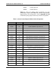
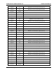
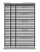
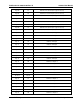
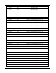
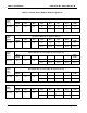
Table 3-2, Control/ Status Register Relay Assignments
Control/
Status
Register
Input Bus to Matrix Bus ‘A’ (lower bus bits 4-0)
Bit 7
(MSB)
Bit 6 Bit 5 Bit 4 Bit 3 Bit 2 Bit 1
Bit 0
(LSB)
Reg. 00A
NC
NC
NC
K5 K4 K3 K2 K1
Bus 4 Bus 3 Bus 2 Bus 1 Bus 0
Control/
Status
Register
Input Bus to Matrix Bus ‘A’ (upper bus bits 9-5)
Bit 7
(MSB)
Bit 6 Bit 5 Bit 4 Bit 3 Bit 2 Bit 1
Bit 0
(LSB)
Reg. 00B
NC
NC
NC
K15 K14 K13 K12 K11
Bus 9 Bus 8 Bus 7 Bus 6 Bus 5
Control/
Status
Register
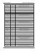
Bypass Matrix Bus ‘A’ to Internal Bus ‘B’ (lower bus bits 4-0)
Bit 7
(MSB)
Bit 6 Bit 5 Bit 4 Bit 3 Bit 2 Bit 1
Bit 0
(LSB)
Reg. 01A
NC
NC
NC
K10 K9 K8 K7 K6
Bus 4 Bus 3 Bus 2 Bus 1 Bus 0
Control/
Status
Register
Bypass Matrix Bus ‘A’ to Internal Bus ‘B’ (upper bus bits 9-5)
Bit 7
(MSB)
Bit 6 Bit 5 Bit 4 Bit 3 Bit 2 Bit 1
Bit 0
(LSB)
Reg. 01B
NC
NC
NC
K20 K19 K18 K17 K16
Bus 9 Bus 8 Bus 7 Bus 6 Bus 5
Control/
Status
Register
Internal Bus ‘B’ to Matrix Bus ‘B’ (lower bus bits 4-0)
Bit 7
(MSB)
Bit 6 Bit 5 Bit 4 Bit 3 Bit 2 Bit 1
Bit 0
(LSB)
Reg. 02A
NC
NC
NC
K25 K24 K23 K22 K21
Bus 4 Bus 3 Bus 2 Bus 1 Bus 0