
Technical data


Publication No. 980673-067 Rev. B 1260-43 User Manual
Astronics Test Systems Installation Instructions 2-5
Front Panel
Connectors
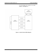
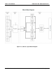
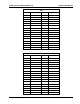
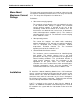
The 1260-43 has six 34-pin front-panel connectors, labeled J200-
J205 and two 20-pin connectors, labeled J206 and J207. Each
matrix consists of a pair of 34-pin connectors. The two 20-pin
connectors are used for bussing the 10-lane buss in and out of the
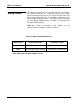
1260-43. The output of the 10-lane buss that connects to J207
incorporates a 3-bit shift to the right. This allows compliancy to the
IFTE specification when daisy-chaining two or more 1260-43’s in a
system and eliminates the need for a special cable. If a 408006
(1260-43) is used, a 602780 cable is required in order to meet the
IFTE specification. See Figure 2-3
for front panel connector
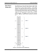
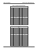
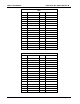
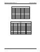
locations. Table 2-1 shows the signal assignments to connector
pins.
Figure 2-3, Front Panel Connector Numbering