
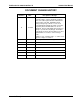
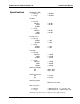
Technical data

1260-43 User Manual Publication No. 980673-067 Rev. B
Installation Instructions 2-2 Astronics Test Systems
Module
Configuration
The 1260-43 is an ultra high-density matrix switch card. Each
module consists of three 8x24, single wire
matrices, which are
interconnected via a 10-lane buss. On-board configuration relays
allow software control of the matrix configuration.
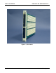
The 1260-43 is comprised of three boards, the 405237, 405249
and the 405250. The main controller board (405249) interfaces to
the VXI buss and thus has all the control logic for communicating
with the buss. In addition the control board decodes the address’s
that select the relay read/write ports. The relay board (405237)
contains 900 relays of which 450 relays are on top with another
450 relays on the bottom. The control board connects to the relay
board via five 200 pin connectors. The connectors pass the relay
coil enabling signals from the control board to the relay board.
The interface board (405250) contains 8 connectors used to
connect to the outside world. The interface board connects to the
relay board using two 80-pin flex cables.
The interface board shifts the ‘Output Buss’ three positions to the
right before connecting to J207. This is transparent to the user and
is done so the 1260-43 is compliant with the IFTE specification
when daisy-chaining two or more 1260-43’s together. This shift
eliminates the need to place the shift in the daisy-chaining cable.
Thus the daisy-chaining cable becomes point-to-point.
If a 408006 (1260-43) is used, a 602780 cable is required in order
to meet the IFTE specification.