
Specifications

1260-14 User Manual
4 Addendum Page 6/98
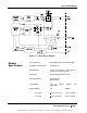
So, for example, a 1260-14 with a module address of 2 would have a base address of 204801
16
,
and the data register for channels 89 through 96 would be at (204801
16
+ 16
16
= 204817
16
)
Each of the data registers controls 8 channels as an 8-bit port. Data written to the port will be
output on the corresponding 8 channels. Data read from the port reflects the present state of the
data on the corresponding 8 channels.
The least significant bit of the port is output to the lowest numbered channel. For example, the
following shows the corresponding bit-to-channel assignment for channels 25 through 32.
Channel 25 Bit 0, LSB
Channel 26 Bit 1
Channel 27 Bit 2
Channel 28 Bit 3
Channel 29 Bit 4
Channel 30 Bit 5
Channel 31 Bit 6
Channel 32 Bit 7 (MSB)
So, by writing the value 25 decimal (= 19 hexadecimal = 0001 1001 binary), we set channels 29,
28, and 25 high and the remaining channels low.
Each of the ports of the 1260-14 must be enabled for written data to appear on the output pins.
Data may be written to the ports without enabling the port, but the data will not be driven on the
output pins until the port is enabled.
The register at offset 18 (hex) from the <Base Address> controls the first 8 ports comprising 64
digital output lines. The register at offset 1A (hex) from the <Base Address> controls the next 4
ports, comprising the highest 32 digital output lines. The bit assignment for these enable registers
is shown below:
Enable Control Register #1 at offset 18
16
from <Base Address>:
Bit 0 (LSB) Enable Port 0 = Channels 1 - 8
Bit 1 Enable Port 1 = Channels 9 - 16
Bit 2 Enable Port 2 = Channels 17 - 24
Bit 3 Enable Port 3 = Channels 25 - 32
Bit 4 Enable Port 4 = Channels 33 - 40
Bit 5 Enable Port 5 = Channels 41 - 48
Bit 6 Enable Port 6 = Channels 49 - 56
Bit 7 (MSB) Enable Port 7 = Channels 57 - 64
Artisan Technology Group - Quality Instrumentation ... Guaranteed | (888) 88-SOURCE | www.artisantg.com