Artisan Technology Group is your source for quality new and certified-used/pre-owned equipment • FAST SHIPPING AND DELIVERY • TENS OF THOUSANDS OF IN-STOCK ITEMS • EQUIPMENT DEMOS • HUNDREDS OF MANUFACTURERS SUPPORTED • LEASING/MONTHLY RENTALS • ITAR CERTIFIED SECURE ASSET SOLUTIONS SERVICE CENTER REPAIRS Experienced engineers and technicians on staff at our full-service, in-house repair center WE BUY USED EQUIPMENT Sell your excess, underutilized, and idle used equipment We also offer credit for buy-back
RACAL INSTRUMENTS 1260-14 DIGITAL I/O MODULE PUBLICATION NO. 980673-003 EADS North America Defense Test and Services, Inc. 4 Goodyear, Irvine, CA 92618 Tel: (800) 722-2528, (949) 859-8999; Fax: (949) 859-7139 info@eads-nadefense.com sales@eads-nadefense.com helpdesk@eads-nadefense.com http://www.eads-nadefense.com PUBLICATION DATE: February 24, 2003 Copyright 1992 by EADS North America Defense Test and Services, Inc. Printed in the United States of America. All rights reserved.
THANK YOU FOR PURCHASING THIS EADS NORTH AMERICA DEFENSE TEST AND SERVICES PRODUCT For this product, or any other EADS North America Defense Test and Services, Inc. product that incorporates software drivers, you may access our web site to verify and/or download the latest driver versions. The web address for driver downloads is: http://www.eads-nadefense.com/downloads If you have any questions about software driver downloads or our privacy policy, please contact us at: info@eads-nadefense.
RETURN of PRODUCT Authorization is required from EADS North America Defense Test and Services, Inc. before you send us your product for service or calibration. Call or contact the Customer Support Department at 1-800-722-3262 or 1949-859-8999 or via fax at 1-949-859-7139. We can be reached at: helpdesk@eads-nadefense.com. PROPRIETARY NOTICE This document and the technical data herein disclosed, are proprietary to EADS North America Defense Test and Services, Inc.
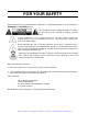
FOR YOUR SAFETY Before undertaking any troubleshooting, maintenance or exploratory procedure, read carefully the WARNINGS and CAUTION notices. This equipment contains voltage hazardous to human life and safety, and is capable of inflicting personal injury. If this instrument is to be powered from the AC line (mains) through an autotransformer, ensure the common connector is connected to the neutral (earth pole) of the power supply.
Artisan Technology Group - Quality Instrumentation ... Guaranteed | (888) 88-SOURCE | www.artisantg.
This page was left intentionally blank. Artisan Technology Group - Quality Instrumentation ... Guaranteed | (888) 88-SOURCE | www.artisantg.
1260-14 User Manual NOTE FOR SYSTEMS WITH 1260-OPT 01T The “Module-Specific Syntax” section of this manual shows the command syntax for the 1260-01S Smart Card. If you are using the newer 1260-01T Smart Card, the commands will NOT work as shown. Consult the 1260-01T Manual for a description of the commands which may be used with the 126001T Smart Card. The channel numbers described in this manual are valid for the 1260-01T. The channel numbers continue to be used for the 1260-01T.
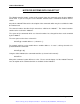
1260-14 User Manual Communicating with a 1260-14 in Register-Based Mode with a 1260-01T The 1260-14 modules are programmed using two basic operations. An 8-bit poke operation is used to write data from the slot 0 controller over the VXIbus backplane to a control register on the switch module. An 8-bit peek operation is used to read data from the status or identification register on the digital I/O module. The 8-bit peeks and pokes are performed using an A24 address.
1260-14 User Manual For example, if the is 204000 (hex), the modules with the addresses 1 through 12 would have the base addresses as shown in the following table. Module Address 1 2 3 4 5 6 7 8 9 10 11 12 Base A24 Address for Module (Hex) 204401 204801 204C01 205001 205401 205801 205C01 206001 206401 206801 206C01 207001 If the base address of the Option-01T is 200000 (hex), then module address 1 would begin at A24 address 200401, module 2 would begin at 200801, and so on.
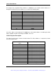
1260-14 User Manual So, for example, a 1260-14 with a module address of 2 would have a base address of 20480116, and the data register for channels 89 through 96 would be at (20480116 + 1616 = 20481716) Each of the data registers controls 8 channels as an 8-bit port. Data written to the port will be output on the corresponding 8 channels. Data read from the port reflects the present state of the data on the corresponding 8 channels.
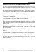
60-14 User Manual Enable Control Register #2 at offset 1A16 hex from Bit 0 Bit 1 Bit 2 Bit 3 Enable Port 8 = Channels 65 - 72 Enable Port 9 = Channels 73 - 80 Enable Port 10 = Channels 81 - 88 Enable Port 11 = Channels 89 - 96 To enable a port of 8 digital output lines, write a 1 to the corresponding bit of the control register. To disable the port, write a 0 to the corresponding bit of the control register.
1260-14 User Manual This page was left intentionally blank. 6 Addendum Page 6/98 Artisan Technology Group - Quality Instrumentation ... Guaranteed | (888) 88-SOURCE | www.artisantg.
1260-14 User Manual Table Of Contents Chapter 1 ...............................................................................................................................1-1 MODULE SPECIFICATION .............................................................................................................1-1 General.........................................................................................................................................1-1 Module Specification .............................
1260-14 User Manual Definition of Commands ...........................................................................................................3-7 PDATAOUT command..........................................................................................................3-7 PSETUP command ...............................................................................................................3-9 READ command .........................................................................................
1260-14 User Manual List Of Figures Figure 1-1, 1260-14 Block Diagram .................................................................................................1-2 Figure 1-2, 1260-14 Front Panel and Pin Configuration ..................................................................1-5 Figure 2-1, 1260-14 .........................................................................................................................2-1 Figure 3-1, 1260-14 Input and Output Handshake Modes.................
1260-14 User Manual This page was left intentionally blank. iv Artisan Technology Group - Quality Instrumentation ... Guaranteed | (888) 88-SOURCE | www.artisantg.
1260-14 User Manual Chapter 1 MODULE SPECIFICATION General The 1260-14 provides 96 TTL or CMOS compatible digital I/O lines in twelve groups of 8 bits each. Each group of 8 bits (hereafter referred to as a port), can be read from or written to asynchronously using the commands READ and WRITE. Additionally, up to 12 ports may be grouped together and synchronously operated using an external clock for as many as 256 consecutive operations by using the appropriate SETUP commands.
1260-14 User Manual Figure 1-1, 1260-14 Block Diagram Module Specification Module Specification 1-2 User Connector Two 50-pin IDC and two 60-pin IDC Number of I/O Channels 96 Channels Configuration I/O lines selected as either input or output on an 8-bit byte basis Data Rate Static to approximately 1 kHz Operating Modes Asynchronous Synchronous Input/Output TTL or CMOS compatible Output Voltage TTL CMOS Vout (High) >2.4 V at -15 mA >3.8 V at 6mA Vout (Low) <0.5 V at 48 mA <0.
1260-14 User Manual Input Voltage Vin (High) >2.0 V >3.15 V Vin (Low) <0.8 V <0.9 V Vih (Max) 5.25 V 5.00 V Cooling Requirement Airflow 1.2 liters/sec Backpressure 0.6 mm of H20 Power Requirement (Ipm) +5V Weight 2.38A (4.78A with Option 01) 2.69 lbs (1.21 kg) 2.97 lbs (1.34 kg with Option 01) Minimum Option 01 Firmware Revision 17.1 * An Open Collector version of the 1260-14 is also available.
1260-14 User Manual Pin Configuration The 1260-14 Digital I/O module has 96 channels, grouped as twelve 8-bit ports available at front panel connectors J1 through J4. Each port may be configured as an input or an output. Refer to Figure 1-2 for the pin configurations of the 50 and 60-pin connectors on the front panel, and to Table 1-1 for correspondence between the physical channel assignments and the port numbers used in the command codes.
1260-14 User Manual J2 J1 CH1 1 2 CH2 3 4 CH3 5 6 CH4 7 8 CH5 9 10 CH6 11 12 CH7 13 14 CH8 15 16 CH9 17 18 CH10 19 20 CH11 21 22 CH12 23 24 CH13 25 26 CH14 27 28 CH15 29 30 CH16 31 32 CH17 33 34 CH18 35 36 CH19 37 38 CH20 39 40 CH21 41 42 CH22 43 44 CH23 45 46 CH24 47 BUSY 49 50 1260-14 FAIL 48 J1 J3 CH25 1 2 CH26 3 4 CH27 5 6 CH28 7 8 CH29 9 10 CH30 11 12 CH31 13 14 CH32 15 16 CH33 17 18 CH34 19 20 CH35
1260-14 User Manual Table 1-2, 1260-14 Pins, Signals and Descriptions J1 Pin Row A Signal Signal Description 1 CH1 Channel 1 I/O 3 CH2 Channel 2 I/O 5 CH3 Channel 3 I/O 7 CH4 Channel 4 I/O . . . . . . . . . 45 CH23 Channel 23 I/O 47 CH24 Channel 24 I/O 49 BSY BUSY Handshake output J1 Pin Row B Signal Signal Description 2 GND Channel 1 RTN 4 GND Channel 2 RTN 6 GND Channel 3 RTN 8 GND Channel 4 RTN . . . . . . . . .
1260-14 User Manual Table 1-2, 1260-14 Pins, Signals and Descriptions (continued) J2 Pin Row A Signal Signal Description 1 CH25 Channel 25 I/O 3 CH26 Channel 26 I/O 5 CH27 Channel 27 I/O 7 CH28 Channel 28 I/O . . . . . . . . . 45 CH47 Channel 47 I/O 47 CH48 Channel 48 I/O 49 CLKIN CLKIN Handshake input J2 Pin Row B Signal Signal Description 2 GND Channel 25 RTN 4 GND Channel 26 RTN 6 GND Channel 27 RTN 8 GND Channel 28 RTN . . . . . . . . .
1260-14 User Manual Table 1-2, 1260-14 Pins, Signals and Descriptions (continued) J3 Pin Row A Signal Signal Description 1 CH49 Channel 49 I/O 3 CH50 Channel 50 I/O 5 CH51 Channel 51 I/O 7 CH52 Channel 52 I/O . . . . . . . . .
1260-14 User Manual Table 1-2, 1260-14 Pins, Signals and Descriptions (continued) J4 Pin Row A Signal Signal Description 1 CH73 Channel 73 I/O 3 CH74 Channel 74 I/O 5 CH75 Channel 75 I/O 7 CH76 Channel 76 I/O . . . . . . . . .
1260-14 User Manual This page was left intentionally blank. Module Specification 1-10 EADS North America Defense Test and Services, Inc. © 1992 Artisan Technology Group - Quality Instrumentation ... Guaranteed | (888) 88-SOURCE | www.artisantg.
1260-14 User Manual Chapter 2 INSTALLATION INSTRUCTIONS Unpacking and Inspection 1. Remove the 1260-14 module and inspect it for damage. If any damage is apparent, inform the carrier immediately. Retain shipping carton and packing material for the carrier’s inspection. 2. Verify that the pieces in the package you received contain the correct 1260-14 module option and the 1260-14 Users Manual. Notify EADS North America Defense Test and Services, Inc. if the module appears damaged in any way.
1260-14 User Manual Reshipment Instructions 1. Use the original packing when returning the switching module to EADS North America Defense Test and Services, Inc. for calibration or servicing. The original shipping carton and the instrument's plastic foam will provide the necessary support for safe reshipment. 2. If the original packing material is unavailable, wrap the switching module in an ESD Shielding bag and use plastic spray foam to surround and protect the instrument. 3.
1260-14 User Manual Chapter 3 MODULE SPECIFIC SYNTAX Asynchronous and Synchronous Modes of Operation Each port on the 1260-14 can operate in either an asynchronous or a synchronous mode. The number of synchronous mode ports may be modified using the SETUP SYNC command. The default after power-up or reset is for all ports to be in the asynchronous mode. The current operating mode of the ports may be determined at any time with the PSETUP command.
1260-14 User Manual Synchronous Mode The synchronous mode of operation allows data to be read from or written to a port in response to a clock edge. Typically, this is done by: 1. Defining the test parameters and data via the various SETUP commands. 2. Arming the test via the SETUP
.ARM ON command. 3. Applying a series of TTL clock inputs to the CLKIN line until the last operation on all ports has been completed, causing the test to automatically disarm.1260-14 User Manual Synchronous Mode Handshaking The module has a two line handshake available for use in the synchronous mode. The first is the BUSY line which is set by the 1260-14 when it is busy processing, and the second is the CLKIN line which the user toggles to clock the next synchronous operation. The user may specify the polarity of the BUSY line and the active edge of the CLKIN line by using the appropriate SETUP command.
1260-14 User Manual OUTPUT HANDSHAKE DATA DATA 01 BSY DATA 02 (1260-14) CLK IN (UUT) tmin INPUT HANDSHAKE BSY CLK IN tp min tsu DATA tn tsu = 25ns tn = 10ns tpmin = 20ns Figure 3-1, 1260-14 Input and Output Handshake Modes Module Specific Syntax 3-4 EADS North America Defense Test and Services, Inc. © 1992 Artisan Technology Group - Quality Instrumentation ... Guaranteed | (888) 88-SOURCE | www.artisantg.
1260-14 User Manual Tri-State Control Each port on the 1260-14 may be either tri-stated or write-enabled. This may be controlled by either hardware, software or both. In hardware, each port has an Enable Driver line (EDRVR 0-11) that is tied to a logic high via an internal pull-up resistor. This allows the software to either tri-state or write-enable the port's driver when requested via the SETUP ENABLE command.
1260-14 User Manual Module Specific Syntax The 1260-14 Digital I/O module supports the PDATAOUT, PSETUP, READ, RESET, SETUP, and WRITE commands. The general form of the module specific syntax for the 1260-14 Digital I/O module is: command address.parameters where: command is one of the 1260-14 module specific commands. address is the module address set by SW1 on the 1260-14 (1-12). parameters are the command specific parameters and data.
1260-14 User Manual All lines must be terminated by an ASCII line feed , EOI or both. Write data may be in either decimal, hexadecimal, or binary format. Non-decimal numbers must be preceded with "H" for hex or "B" for binary. Definition of Commands PDATAOUT command Syntax: PD[ATAOUT] [.][, [.],...] ::= Module address of the 1260-14 (1-12) ::= One or more consecutive ports to return data from.
1260-14 User Manual NOTE: There is a space following the period on each line except for the line containing the END string. This allows the user to detect when the last line of a multiple line reply has occurred by looking at the fifth character of each line to see if it is a space or an ASCII "E". This convention is true for all commands returning multiple line outputs. Output data for the specified modules and ports are in the same order as requested in the command.
1260-14 User Manual would return the following data: 001. 1260-14 DIGITAL INPUT/OUTPUT MODULE 001. 00:9F,7F,3F,1F 001. 01:21,31,41,51 001. 02:7AA6 001. 04:10101101 001.END PSETUP command Syntax: PS[ETUP] ::= Module address of the 1260-14 (1-12) Description: This command will cause the module to return the condition of all the setup variables for the 1260-14 at the specified module address.
1260-14 User Manual X with commas. Bit 0 is the LSB and bit 7 the MSB. A "B" specifies that the output format for the data is binary. Note that this format is unavailable in the fast byte mode to keep the output on a single 80-character line. An "H" specifies that the output format for the data is hexadecimal. A "Y" causes a byte-wide (8-bit) read of the port. This is the default if no width is specified. See Example 1 above for a sample of a byte-wide READ command.
1260-14 User Manual 001. 05: 23 001. 06: 0 001. 07: 127 001.END Example 2: Assume that all ports are defined as asynchronous and are tristated, port 0 is sensing a hex 1e, port 1 is sensing a hex c7, port 2 is sensing a hex d3, port 3 is sensing a hex a0 and the user sends the following command: READ 1.0-2,W,H The user would read back: 001. 1260-14 DIGITAL INPUT/OUTPUT MODULE 001. 00: C71E 001. 02: A0D3 001.
1260-14 User Manual transfer the read data. It is identical to the standard byte width read with the exception that binary formatting is not available, and the output contains no header line, END line, module address or port numbers. All the output line contains is the port data separated by commas. Data is returned in least significant port to most significant port order. This type of read is only available on firmware revisions 18.1 or later.
1260-14 User Manual SETUP ARM command Syntax: SE[TUP]
.AR[M],ON | OFF ::= Module address of the 1260-14 (1-12) Description: This command is used to arm and disarm the synchronous handshake mode. Setup data may only be modified while ARM is OFF. Synchronous data transfers may only take place when ARM is ON. Once the card is armed, any attempts to send a setup command other than a SETUP .ARM,OFF will cause an error.1260-14 User Manual NOTE: The BUSY line is only valid when synchronous operations are defined and armed. Spurious signals at other times should be ignored by the user. Example: This command sets the polarity of the BUSY signal to negative within the module at address 2. SETUP 2.BUSY,NEG SETUP CLKIN command Syntax: SE[TUP]
.CL[KIN],POS | NEG ::= Module address of the 1260-14 (1-12) Description: This command defines the active edge of the CLKIN handshake signal.1260-14 User Manual SETUP ENABLE command Syntax: SE[TUP]
.EN[ABLE][,,,...] ::= Module address of the 1260-14 (1-12) ::= One or more consecutive ports to write to. A single port is specified as a decimal number from 0 to 11. A group of ports is specified as two decimal numbers from 0 to 11 separated by a hyphen, (-), with the lower numbered port to the left and the higher numbered port to the right. For example, the command SE 1.1260-14 User Manual SETUP RD command Syntax: Byte: SE[TUP]
.RD,[,Y][,B | ,H], Word: SE[TUP] .RD,,W[,B | ,H], Bit: SE[TUP] .RD,,X [,X...1260-14 User Manual Read operations may be performed as either bit, byte or word width operations, with byte width being the default. Data will be formatted in either decimal, hexadecimal or binary, with the default being decimal. The width and format of the output are specified as follows: A "B" specifies that the output format for the data is binary. An "H" specifies that the output format for the data is hexadecimal. A "Y" specifies a byte-wide (8-bit) read of the port.
1260-14 User Manual Example 3: Assume that port 0 is a synchronous port and the user sends the following command: SETUP 1.RD 0,X5,X7,X1,10 This command would cause the module to perform a bit-wide read of bits 5, 7 and 1 for ten vector on port 0 during the next synchronous test. SETUP SYNC command Syntax: SE[TUP]
.1260-14 User Manual The asynchronous WRITE command will work normally on a synchronous port, but the READ command will not. This allows the user to preset the value of the port prior to the beginning synchronous operations. Note that this may only be done while the synchronous mode is not armed. SETUP WR command Syntax: Byte: SE[TUP]
.WR,[,Y][, ,...,] Word: SE[TUP] .WR,[,W][, ,...,] Bit: SE[TUP] .WR,[,X][, ;...1260-14 User Manual operations. When a width change is requested by using either the "W", "X" or "Y" width designator, the port’s buffer is cleared of all previous data and the new data is loaded starting at vector 1. If there is no width designator, the port remains in its current mode, and the new data is appended to the existing data in the buffer for up to a maximum of 256 vectors of data.
1260-14 User Manual wide operations are specified on even-numbered ports only, and place the least significant 8 bits in the even port and the most significant 8 bits in the following odd-numbered port. Word sized operations may not be mixed with bit or byte operations in either the even or odd port.
1260-14 User Manual specify that bit 3 will go high in vector 1, bit 1 will go high and bit 3 will go low in vector 2, and bits 5 and 7 will go high in vector 3. The second SETUP statement will leave the buffer intact and will specify that in vector 4, bits 1 and 7 will go low. Once the test is armed, port 0 would be actively driving a binary 00001000 after the first clock, a 00000010 after the second, a 10100010 after the third and a 00100000 after the last clock.
1260-14 User Manual NOTE: Care should be used not to change the width when writing to a synchronous port if the port has already had its width defined and data loaded into the buffer. In this case, the user should not specify a width, and should format the WRITE data in the same size that the synchronous port was defined at. Failure to do so will cause the port to change its width designation, and will clear the data in the buffer.
1260-14 User Manual wide operations are specified on even-numbered ports only, and place the least significant 8 bits in the even-numbered port and the most significant 8 bits in the following odd-numbered port. Wordwide operations may not be mixed with bit or byte-wide operations in either the even or odd port. Example 2: Assume that ports 5-11 are defined as asynchronous and the user sends the following command: WR 1.
1260-14 User Manual Synchronous Mode Example The following is an example of an 8-vector synchronous read/write operation using a 1260-14 at address 1: 1. SE 1.SY,2 Sets up ports 0 and 1 for SYNC mode; ports 2-11 will be in ASYNC mode. 2. SE 1.RD 0,8 Tells the module to read data into first eight buffer locations of port 0 when clocked. 3. SE 1.WR 1,Y,1,2,3,4 Sets port 1 into the byte mode and loads write data into its first four buffer locations. 4. SE 1.
1260-14 User Manual This page was left intentionally blank. Module Specific Syntax 3-26 EADS North America Defense Test and Services, Inc. © 1992 Artisan Technology Group - Quality Instrumentation ... Guaranteed | (888) 88-SOURCE | www.artisantg.
1260-14 User Manual Chapter 4 OPTIONAL HARNESS ASSEMBLIES The following harness assemblies are used to connect 1260-14 to Freedom Series Test Receiver Interfaces. Each harness documentation consists of an assembly drawing, parts list, system wire list and wire list. 407272 Virginia Panel, Inc. Series VP90 Interface Harness 407273 TTI Testron, Inc. Interface Harness For more information on complete line of Test Receivers Interface solution, contact your Sales Representative.
1260-14 User Manual This page was left intentionally blank. Optional Harness Assemblies 4-2 EADS North America Defense Test and Services, Inc. © 1992 Artisan Technology Group - Quality Instrumentation ... Guaranteed | (888) 88-SOURCE | www.artisantg.
EADS North America Defense Test and Services, Inc. © 1992 (P2) P2 J2 (P2) J101 J101 (P2) J3 4 1.7 MAX 3 PLCS PIN 1 (P3) (P2) J100 3 2 11.0± 1.0 2 PLCS J1 3 2 2 1 3 PLCS 36.0 ± 2.0 9 8 39.0± 2.0 3 PLCS 11 10 7 6 AR 10 PLCS 2 AR 6 PLCS 407272 REV. 8 7 2 AR 4 PLCS FAR SIDE 2 REQD 5 J2 (P1) 3 3 4 PIN 1 2 ZONE J4 (P1) J3 (P1) PIN 1 8 PIN 1 PIN 1 2.0 ± .2 AR Artisan Technology Group - Quality Instrumentation ... Guaranteed | (888) 88-SOURCE | www.
1260-14 User Manual ENGINEERING PARTS LIST ITEM BIN PART NO. DESCRIPTION U/M QTY REFERENCE 1 405084 PCB AS SY, VP90 INTFC,64PIN EA 1.00000 J102 2 405085 PCB ASSY, VP90 1NTFC,96PIN EA 2.00000 J100-J101 3 407251 CABLE ASSY, DC, 50-COND., VP90 EA 1.00000 4 407256 CABLE ASSY, DC, 60-COND., VP90 EA 2.00000 5 407252 CABLE ASS Y, 50SPLT, VP90 EA 1.00000 6 910541 POLYURETHANE CONF. COAT EA .00001 7 GRP-110-1/2 TBGOV-Poy.250ID-BLACK FT .
1260-14 User Manual ENGINEERING PARTS LIST WIRE FROM TO TYPE PART # BLK AA (J100) Uxx-SLOT yy (J1,J2) CABLE 407272 BLK AA (J101) Uxx-SLOT yy (J2,J3) CABLE 407272 BLK AA (J102) Uxx-SLOT yy (J4) CABLE 407272 WIRE LEN REFERENCE SYSTEM WIRE LIST This system wirelist serves as a template for incorporating this harness assembly into the overall system wirelist. It does not in any way affect the fabrication of this harness assembIy. RACAL Instruments, Inc., 4 Goodyear St.
1260-14 User Manual ENGINEERING WIRE LIST WIRE FROM TO TYPE PART # WIRE LEN REFERENCE 1 2 J100-96 J100-32 J1-1 J1-2 BRN TAN 407251 407251 41.5" 41.5" CHAN 01 CHAN 01 RTN 3 J100-64 J1-3 RED 407251 41.5" CHAN 02 4 J100-95 J1-4 TAN 407251 41.5" CHAN 02 RTN 5 J100-31 J1-5 ORN 407251 41.5" CHAN 03 6 J100-63 J1-6 TAN 407251 41.5" CHAN 03 RTN 7 J100-94 J1-7 YEL 407251 41.5" CHAN 04 8 J100-30 J1-8 TAN 407251 41.5" CHAN 04 RTN 9 J100-62 J1-9 ORN 407251 41.
1260-14 User Manual ENGINEERING WIRE LIST WIRE FROM TO 51 52 J100-48 J100-79 NO CONNECT NO CONNECT TYPE PART # WIRE LEN REFERENCE 53 54 J100-15 J100-47 NO CONNECT NO CONNECT 55 56 J100-78 J100-14 NO CONNECT NOCONNECT 57 58 J100-46 J100-77 NO CONNECT NO CONNECT 59 60 J100-13 J100-45 NO CONNECT NO CONNECT 61 62 J100-76 J100-12 NO CONNECT NO CONNECT 63 64 J100-44 J100-75 NO CONNECT NO CONNECT 65 66 J100-11 J100-43 NO CONNECT NO CONNECT 67 68 J100-74 J100-10 NO CONNECT NO CONNEC
1260-14 User Manual ENGINEERING WIRE LIST WIRE FROM TO TYPE PART # WIRE LEN REFERENCE 97 98 J101-72 J101-8 J2-27 J2-28 YEL TAN 407252 407252 41.5" 41.5" CHAN 38 CHAN 38 RTN 99 100 J10140 J101-71 J2-29 J2-30 GRN TAN 407252 407252 41.5" 41.5" CHAN 39 CHAN 39 RTN 101 102 J101-7 J101-39 J2-31 J2-32 BLU TAN 407252 407252 41.5" 41.5" CHAN 40 CHAN 40 RTN 103 104 J101-70 J101-6 J2-33 J2-34 VIO TAN 407252 407252 41.5" 41.
1260-14 User Manual ENGINEERING WIRE LIST WIRE FROM TO TYPE PART # WIRE LEN REFERENCE 145 146 J101-88 J101-24 J3-25 J3-26 ORN TAN 407256 407256 41.5" 41.5" CHAN 61 CHAN 61 RTN 147 148 J101-56 J101-87 J3-27 J3-28 YEL TAN 407256 407256 41.5" 41.5" CHAN 62 CHAN 62 RTN 149 150 J101-23 J101-55 J3-29 J3-30 ORN TAN 407256 407256 41.5" 41.5" CHAN 63 CHAN 63 RTN 151 152 J101-86 J101-22 J3-31 J3-32 BLU TAN 407256 407256 41.5" 41.
1260-14 User Manual ENGINEERING WIRE LIST WIRE FROM TO TYPE PART # WIRE LEN REFERENCE 193 J102-64 J4-1 BRN 407256 41.5" CHAN 73 194 J102-32 J4-2 TAN 407256 41.5" CHAN 73 RTN 195 196 J102-63 J102-31 J4-3 J4-4 RED TAN 407256 407256 41.5" 41.5" CHAN 74 CHAN 74 RTN 197 198 J102-62 J102-30 J4-5 J4-6 ORN TAN 407256 407256 41.5" 41.5" CHAN 75 CHAN 75 RTN 199 200 J102-61 J102-29 J4-7 J4-8 YEL TAN 407256 407256 41.5" 41.
1260-14 User Manual ENGINEERING WIRE LIST WIRE FROM TO TYPE PART # WIRE LEN REFERENCE 243 244 J102-39 J102-7 J4-51 J4-52 BLU TAN 407256 407256 41.5" 41.5" EDRVR 07IVEXT 08 EDRVR 07IVEXT 08 RTN 245 246 J102-38 J102-6 J4-53 J4-54 VIO TAN 407256 407256 41.5" 41.5" EDRVR 08/VEXT 09 EDRVR 08/VEXT 09 RTN 247 248 J102-37 J102-5 J4-55 J4-56 GRY TAN 407256 407256 41.5" 41.5" EDRVR 09/VEXT 10 EDRVR 09/VEXT 10 RTN 249 250 J102-36 J1024 J4-57 J4-58 WHT TAN 407256 407256 41.5" 41.
1260-14 User Manual Optional Harness Assemblies 4-12 EADS North America Defense Test and Services, Inc. © 1992 Artisan Technology Group - Quality Instrumentation ... Guaranteed | (888) 88-SOURCE | www.artisantg.
1260-14 User Manual ENGINEERING PARTS LIST ITEM BIN PART NO. DESCRIPTION QTY 1 407250 CABLE ASSY, IDC, 50-COND, TTI 2 2 407255 CABLE ASSY, IDC, 60-COND, TTI 2 3 610777 TIE-CA-LKG-.062-.075 A/R 4 910541 POLYURETHANE CONFORMAL COAT A/R REFERENCE RACAL Instruments, Inc., 4 Goodyear St., Irvine, CA 92718 DOCUMENT TI'I'LE SIZE. CODE NO DOCUMENT NO. REV HARNESS ASSY, 1260-14,TTI A 21793 407273 A DRN EADS North America Defense Test and Services, Inc.
1260-14 User Manual ENGINEERING WIRE LIST WIRE FROM TO TYPE PART # BLK AAx RW 0l (J100) Uxx-SLOT yy (JI) CABLE 407273 BLK AAx RW 02 (3101) Uxx-SLOT yy (J1) CABLE 407273 BLK AAx RW 03 (J102) Uxx-SLOT yy (J1) CABLE 407273 BLK AAx RW 04 (J103) Uxx-SLOT yy (JI) CABLE 407273 BLK AAx Rw 05 (J104) Uxx-S LOT yy (J1) CABLE 407273 BLK AAx RW 06 (J105) Uxx-S LOT yy (J2) CABLE 407273 BLK AAx RW 07 (J106) Uxx-SLOT yy (J2) CABLE 407273 BLK AAx RW 08 (J107) Uxx-SLOT yy (J2) CABLE 407273
1260-14 User Manual ENGINEERING WIRE LIST WIRE 1 2 3 4 5 6 7 8 9 10 11 12 13 14 15 16 17 18 19 20 21 22 23 24 25 26 27 28 29 30 31 32 33 34 35 36 37 38 39 40 41 42 43 44 45 46 47 48 49 50 FROM J100-1 J100-2 J100-3 J100-4 J100-5 J100-6 JJ00-7 J100-8 J100-9 J100-10 J101-10 J101-9 J101-8 J101-7 J101-6 J101-5 J101-4 J101-3 J101-2 J101-1 J102-1 J102-2 J102-3 J102-4 J102-5 J102-6 J102-7 J102-8 J102-9 J102-10 J103-10 J103-9 J103-8 J103-7 J103-6 J103-5 J103-4 J103-3 J103-2 J103-1 J104-1 J104-2 J104-3 J104-4 J104-5
1260-14 User Manual ENGINEERING WIRE LIST WIRE FROM TO TYPE PART # WIRE LEN REFERENCE 51 52 J105-1 J105-2 J2-1 J2-2 BRN TAN 407250 407250 41.5" 41.5" CHAN2S CHAN 25 RTN 53 54 J105-3 J105-4 J2-3 J2-4 RED TAN 407250 407250 41.5" 41.5" CHAN 26 CHAN 26 RTN 55 56 J105-5 J105-6 J2-5 J2-6 ORN TAN 407250 407250 41.5" 41.5" CHAN 27 CHAN 27 RTN 57 58 J105-7 J105-8 J2-7 J2-8 YEL TAN 407250 407250 41.5" 41.
1260-14 User Manual ENGINEERING WIRE LIST WIRE FROM TO TYPE PART # WIRE LEN REFERENCE 100 J109-9 J109-10 J2-49 J2-50 ORN TAN 407250 407250 41.5" 41.5" CLOCK IN CLOCK IN RTN 101 102 J110-1 J110-2 J3-1 J3-2 BRN TAN 407255 407255 41.5" 41.5" CHAN 49 CHAN 49 RTN 103 104 J110-3 J110-4 J3-3 J3-4 RED TAN 407255 407255 41.5" 41.5" CHAN 50 CHAN 50 RTN 105 106 J110-5 J110-6 J3-5 J3-6 ORN TAN 407255 407255 41.5" 41.
1260-14 User Manual ENGINEERING WIRE LIST WIRE FROM TO TYPE PART # WIRE LEN REFERENCE 147 148 J114-7 J114-8 J3-47 J3-48 YEL TAN 407255 407255 41.5" 41.5" CHAN 72 CHAN 72 RTN 149 150 J114-9 J114-10 J3-49 J3-50 GRN TAN 407255 407255 41.5" 41.5" EDRVR 00 EDRVR 00 RTN 151 152 J115-10 J115-9 J3-51 J3-52 BLU TAN 407255 407255 41.5" 41.5" EDRVR 01 EDRVR 01 RTN 153 154 J115-8 J115-7 J3-53 J3-54 VIO TAN 407255 407255 41.5" 41.
1260-14 User Manual ENGINEERING WIRE LIST WIRE FROM TO TYPE PART # WIRE LEN REFERENCE 195 196 J119-6 J119-5 J4-35 J4-36 GRY TAN 407255 407255 41.5" 41.5" CHAN 90 CHAN 90 RTN 197 198 J119-4 J119-3 J4-37 J4-38 WHT TAN 407255 407255 41.5" 41.5" CHAN 91 CHAN 91 RTN 199 200 J119-2 J119-1 J4-39 J4-40 BLK TAN 407255 407255 41.5" 41.5" CHAN 92 CHAN 92 RTN 201 202 J120-1 J120-2 J4-41 J4-42 BRN TAN 407255 407255 41.5" 41.
1260-14 User Manual This page was left intentionally blank. Optional Harness Assemblies 4-20 EADS North America Defense Test and Services, Inc. © 1992 Artisan Technology Group - Quality Instrumentation ... Guaranteed | (888) 88-SOURCE | www.artisantg.
1260-14 User Manual Chapter 5 PRODUCT SUPPORT Product Support EADS North America Defense Test and Services, Inc. has a complete Service and Parts Department. If you need technical assistance or should it be necessary to return your product for repair or calibration, call 1-800-722-3262. If parts are required to repair the product at your facility, call 1-949-859-8999 and ask for the Parts Department. When sending your instrument in for repair, complete the form in the back of this manual.
1260-14 User Manual REPAIR AND CALIBRATION REQUEST FORM To allow us to better understand your repair requests, we suggest you use the following outline when calling and include a copy with your instrument to be sent to the EADS North America Defense Test and Service, Inc. Repair Facility. Model Serial No.
Artisan Technology Group is your source for quality new and certified-used/pre-owned equipment • FAST SHIPPING AND DELIVERY • TENS OF THOUSANDS OF IN-STOCK ITEMS • EQUIPMENT DEMOS • HUNDREDS OF MANUFACTURERS SUPPORTED • LEASING/MONTHLY RENTALS • ITAR CERTIFIED SECURE ASSET SOLUTIONS SERVICE CENTER REPAIRS Experienced engineers and technicians on staff at our full-service, in-house repair center WE BUY USED EQUIPMENT Sell your excess, underutilized, and idle used equipment We also offer credit for buy-back