
Technical data


Publication No. 980824-118 Rev. A 1260-118/-118A User Manual
Astronics Test Systems Module Operation 3-5
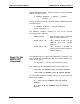
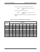
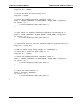
Table 3-2, 1260-118A Control Register Channel Assignments
Control
Register
Channels
Bit 7
(MSB)
Bit 6 Bit 5 Bit 4 Bit 3 Bit 2 Bit 1
Bit 0
(LSB)
0
unused
unused
unused
unused
2
1
0
unused
1
unused
unused
5
4
3
unused
unused
unused
2
8
7
6
unused
unused
unused
unused
unused
3
9
unused
unused
unused
unused
unused
unused
unused
4
unused
unused
unused
unused
unused
unused
11
10
5
unused
unused
unused
unused
14
13
12
unused
6
unused
unused
17
16
15
unused
unused
unused
7
20
19
18
unused
unused
unused
unused
unused
8
21
unused
unused
unused
unused
unused
unused
unused
9
unused
unused
unused
unused
unused
unused
23
22
For the 1260-118 setting a control bit to 1 closes the corresponding
channel, and clearing the bit to zero opens the corresponding
channel. Thus, if you write the value 1000 0101 binary = 133
decimal = 85 hexadecimal to Control Register 0
, channels 0, 2,
and 7 will close, while channels 1, 3, 4, 5, and 6 will open.
Unlike the 1260-
118, not all bits in the control registers are used.
Thus, for the 1260-118A if you write the value 1000 0101 binary =
133 decimal = 85 hexadecimal to Control Register 0, only channel
1 will close, while channels 0 and 2 will open.
The present control register value may be read back by reading an
8-bit value from the control register address.
The value is
inverted. In other words, the eight-bit value read back is the one’s
complement of the value written. If an unused bit in the control
register is set to 1 it will give a 0 readback.
If you want to change the state of a single relay without affecting
the present state of the other relays controlled by the control
register, you must:
1. Read the control register
2.
Invert the bits (perform a one’s complement on the register
data)
3. Perform a bit-
wise AND operation, leaving all but the specific
control register bit for the relay to change
4. To open: continue to step 5. To close: OR in the bit for the